Radiator

A heat dissipation device and heat sink technology, which is applied in cooling/ventilation/heating transformation, instruments, electrical digital data processing, etc., can solve the problem of poor heat dissipation effect, poor heat dissipation efficiency, and inability to effectively utilize the heat dissipation area of ​​heat sink A, etc. problems, to achieve the effect of reducing noise, reducing wind resistance, and increasing air volume

Inactive Publication Date: 2013-12-18
DONG GUAN YUNG TENG ELECTRONICS PROD
View PDF4 Cites 8 Cited by
  • Summary
  • Abstract
  • Description
  • Claims
  • Application Information

AI Technical Summary

Problems solved by technology

[0003] Furthermore, the current common practice in the industry is to attach the heat sink to the heat source on the circuit board (such as the central processing unit, image processor, chip, etc.), and after the fan is positioned on the heat sink, the fan can be connected to the heat sink. The heat sink is matched to form an optimized heat dissipation structure, please refer to Figure 8 Shown is the three-dimensional exploded view of the existing heat sink. It can be clearly seen from the figure that most of the heat sinks A used today are made of integral molding (such as aluminum extrusion, molding), and the heat sink A Standing upward from the base A1 are a plurality of fins A2 in a spaced shape, and the arrangement of the fins A2 is a flat surface, and the fan C is installed on the flat upper surface of the fins A2 for positioning. The heat sink A is installed on the circuit board B, and the base A1 is attached to the upper surface of the chip B1, so as to facilitate the conduction of the heat energy of the chip B1 to the heat sink A. However, when the fan C is running to blow axial air, the axial flow The wind is blown in a spiral and downward manner, so that the wind after heat exchange can escape outwards through the channel formed between the adjacent fins A2, but because the base A1 of the heat sink A and the chip B1 contact the middle The part absorbs more heat energy, and conducts the heat energy to the surroundings of the base A1 and the plurality of fins A2, so that the fins A2 in the center of the base A1 absorb heat energy faster than the fins A2 in the periphery, so that The heat is stored in the center of the heat sink A, which cannot effectively utilize the overall heat dissipation area of ​​the heat sink A and the heat dissipation effect is also poor
[0004] In addition, the heat sink A has a plurality of fins A2 on the base A1 to increase the overall heat dissipation area, and the base A1 is limited by the area requirement, which will make the arrangement of the plurality of fins A2 denser, so , the downward blowing axial flow generated by the operation of the fan C will be affected and cannot smoothly enter the channel between the adjacent fins A2 to form wind resistance and generate great noise, and because the upper surface of the fins A2 is flat The design of the same height causes the axial flow wind to concentrate at the center of the multiple fins A2 at a constant speed, and can only dissipate heat from the part of the heat sink A, so that the heat energy will still be stored in the center of the heat sink A, and cannot Effective heat dissipation results in poor heat dissipation efficiency
[0005] Therefore, the above-mentioned existing heat sinks really have room for improvement, and those who are engaged in this industry need to redesign to effectively solve the problem.

Method used


Image

  • Radiator
  • Radiator
  • Radiator

Examples


Embodiment Construction

[0026] In order to achieve the above-mentioned purpose and effect, the technical means and the structure adopted by the present invention are hereby illustrated in detail with respect to the preferred embodiments of the present invention. The features and functions are as follows for a complete understanding.

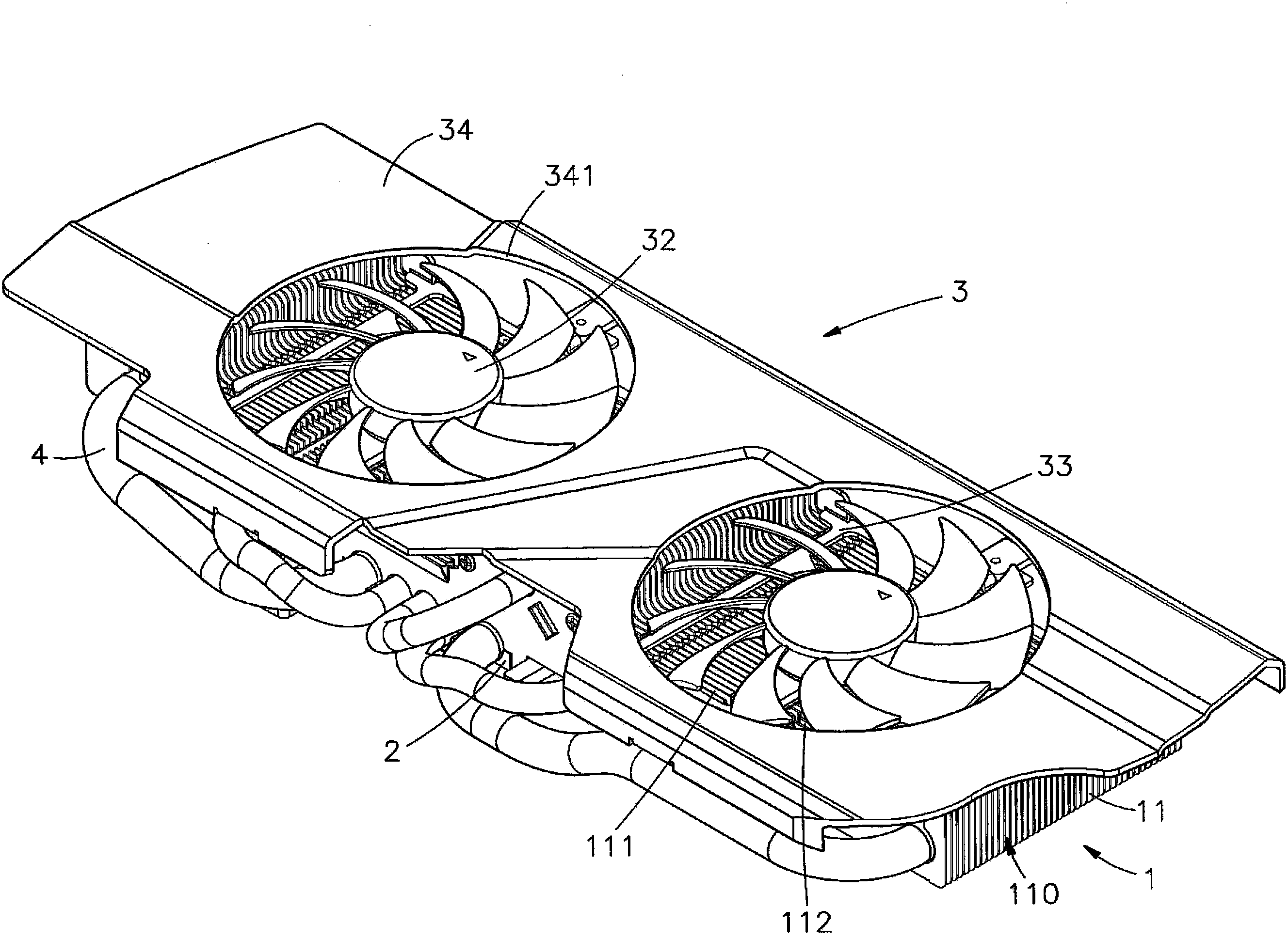
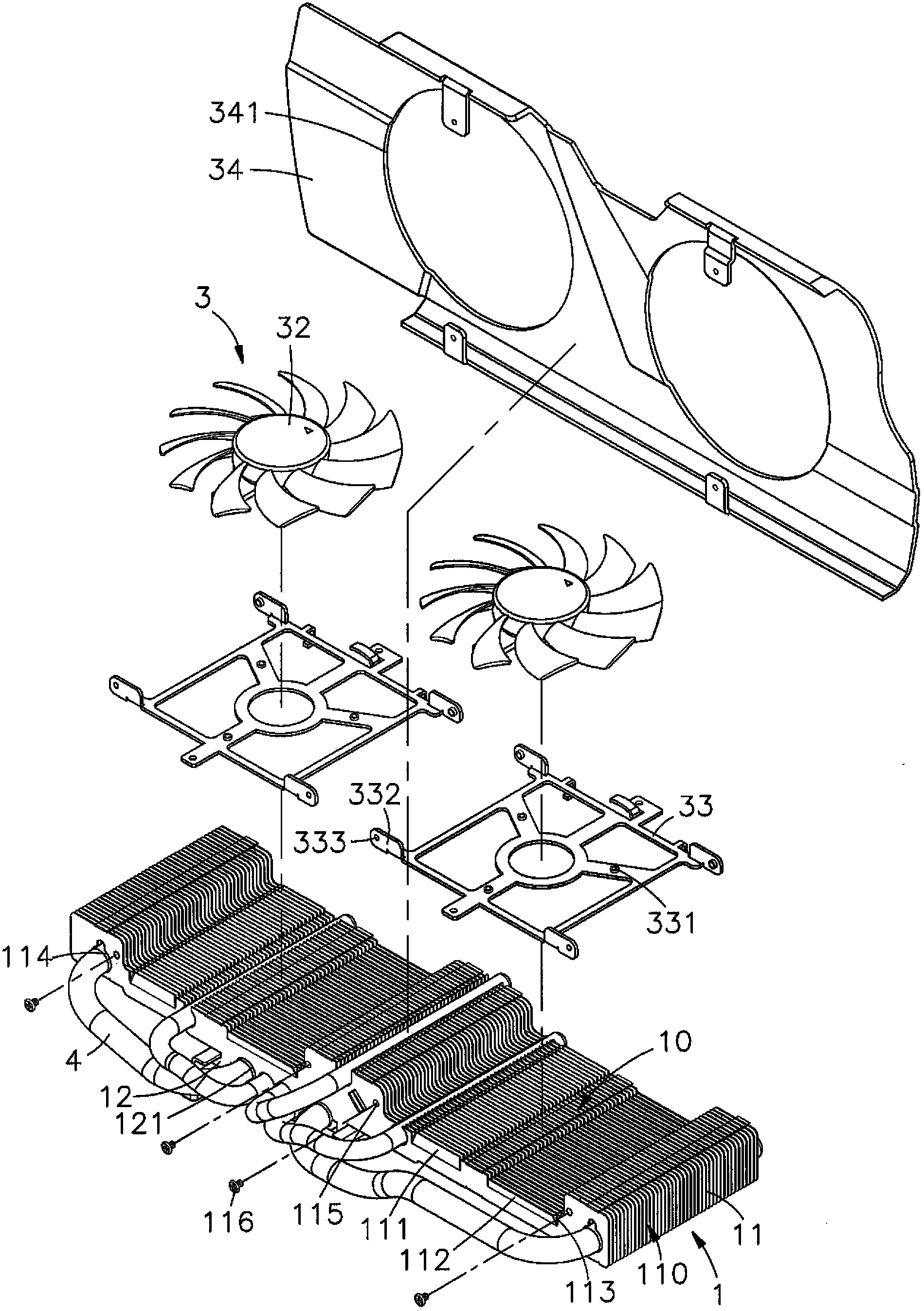
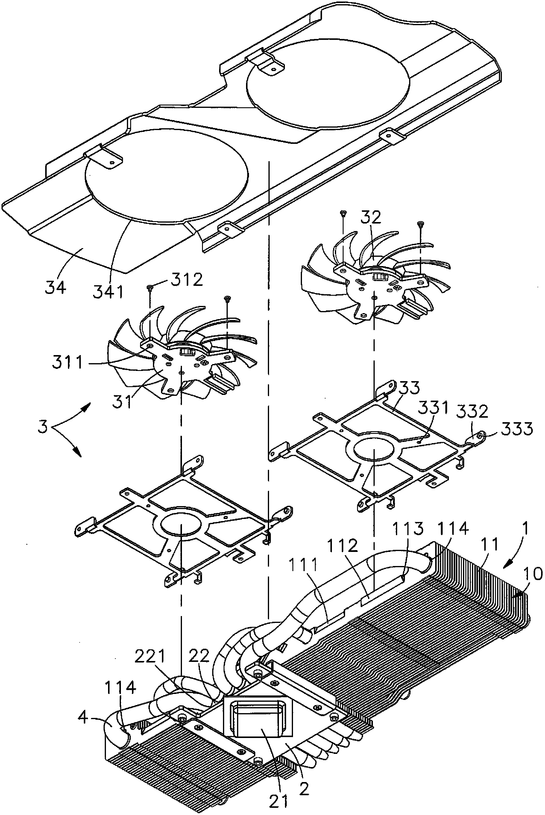
[0027] see figure 1 , figure 2 , image 3 , Figure 4 , Figure 5 As shown, they are respectively the three-dimensional appearance diagram, the three-dimensional exploded view, the three-dimensional exploded view of another angle of view, the three-dimensional exploded view of the heat sink and the side sectional view of the present invention. It can be clearly seen from the figure that the present invention includes a heat dissipation Sheet 1, heat sink 2 and fan 3, so the main components and features of the present invention are described in detail as follows, wherein:

[0028] The heat sink 1 has a plurality of fins 11 arranged at intervals, and at least one re...


PUM


Abstract

The invention relates to a radiator which comprises cooling fins, a heat sink and a fan. The heat sink which can be attached to a heating source on a circuit board in an abutting mode is arranged below the multiple cooling fins. A heat dissipation channel is formed between every two adjacent fins. At least two guide sheets, namely the first guide sheet and the second guide sheet extend obliquely upward from a board above each fin, wherein a preset inclination angle is formed between the first guide sheet and the second guide sheet in opposite directions. The fan is positioned above the fins. When the fan operates to blow axial wind onto the cooling fins, the first guide sheets and the second guide sheets on the fins are made to face the axial wind generated by the fan to enhance the windward effect so as to lower the wind resistance of the fins, reduce the noise generated during the blowing by the fan, and increase the air volume in the heat dissipation channels. Therefore, heat energy can be quickly taken out and diffused, and the overall heat dissipation effect is better.

Description

technical field [0001] The invention provides a heat dissipation device, especially a first guide piece and a second guide piece with a predetermined angle of inclination in opposite directions extending obliquely upward on the upper plate surface of a plurality of fins of the heat sink, and facing the axis of the fan. Flow air, to reduce its wind resistance to reduce the noise generated, so that the air volume increases and the heat dissipation effect is better. Background technique [0002] Nowadays, computer technology is growing at an ever-changing speed, which makes the development trend of computers move towards the direction of powerful computing functions and fast speed. The generated temperature is higher, so how to use a good heat dissipation system to make the computer work normally at its allowable temperature has been regarded as an extremely important issue by the industry. For better heat dissipation efficiency and manufacturing cost, the fins of the heat sin...

Claims


Application Information

Patent Timeline
Patent Type & Authority Applications(China)
IPC IPC(8): H05K7/20G06F1/20
Inventor 陈恒隆林义坤
Owner DONG GUAN YUNG TENG ELECTRONICS PROD
Why Eureka
Try Eureka