
Light-guide module and related light sensing device

A light guide module, light detection technology, applied in lighting devices, lighting device parts, instruments, etc., can solve problems such as no other types of applications

Active Publication Date: 2013-12-18
PIXART IMAGING INC
View PDF3 Cites 0 Cited by
  • Summary
  • Abstract
  • Description
  • Claims
  • Application Information

AI Technical Summary

Problems solved by technology

However, the traditional side-type light guide plate is only used in the backlight module, and there are no other types of applications

Method used


Image

  • Light-guide module and related light sensing device
  • Light-guide module and related light sensing device
  • Light-guide module and related light sensing device

Examples


Embodiment Construction

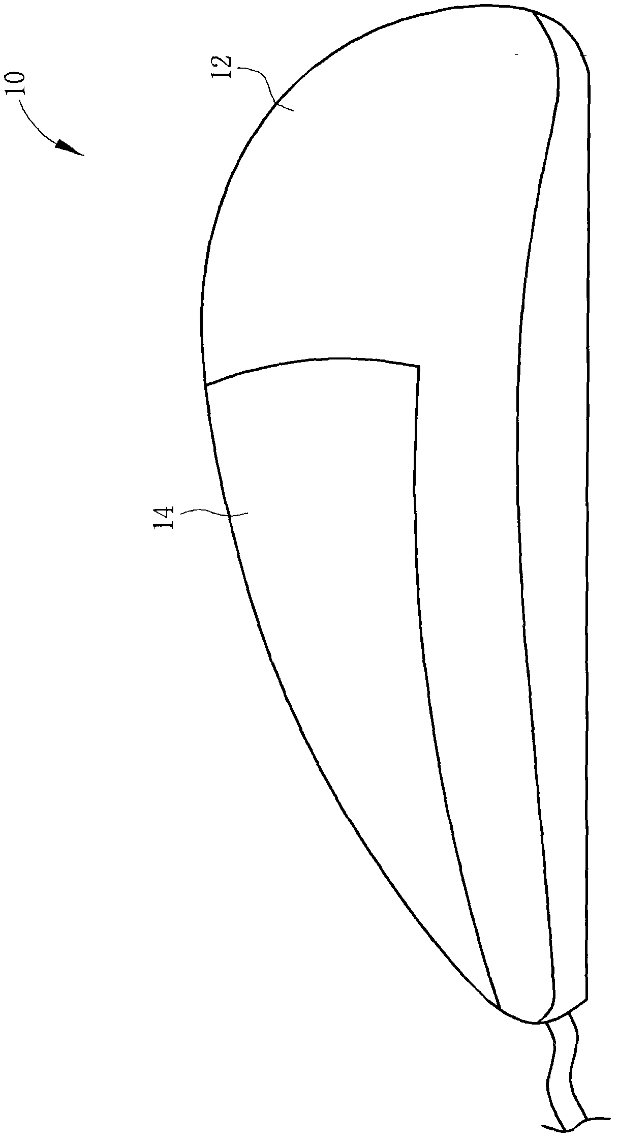
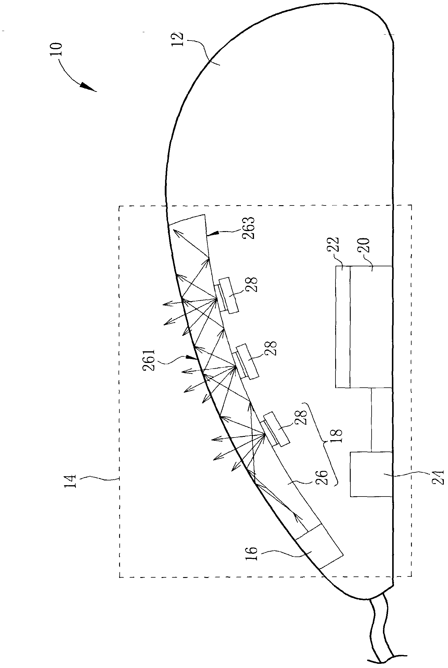
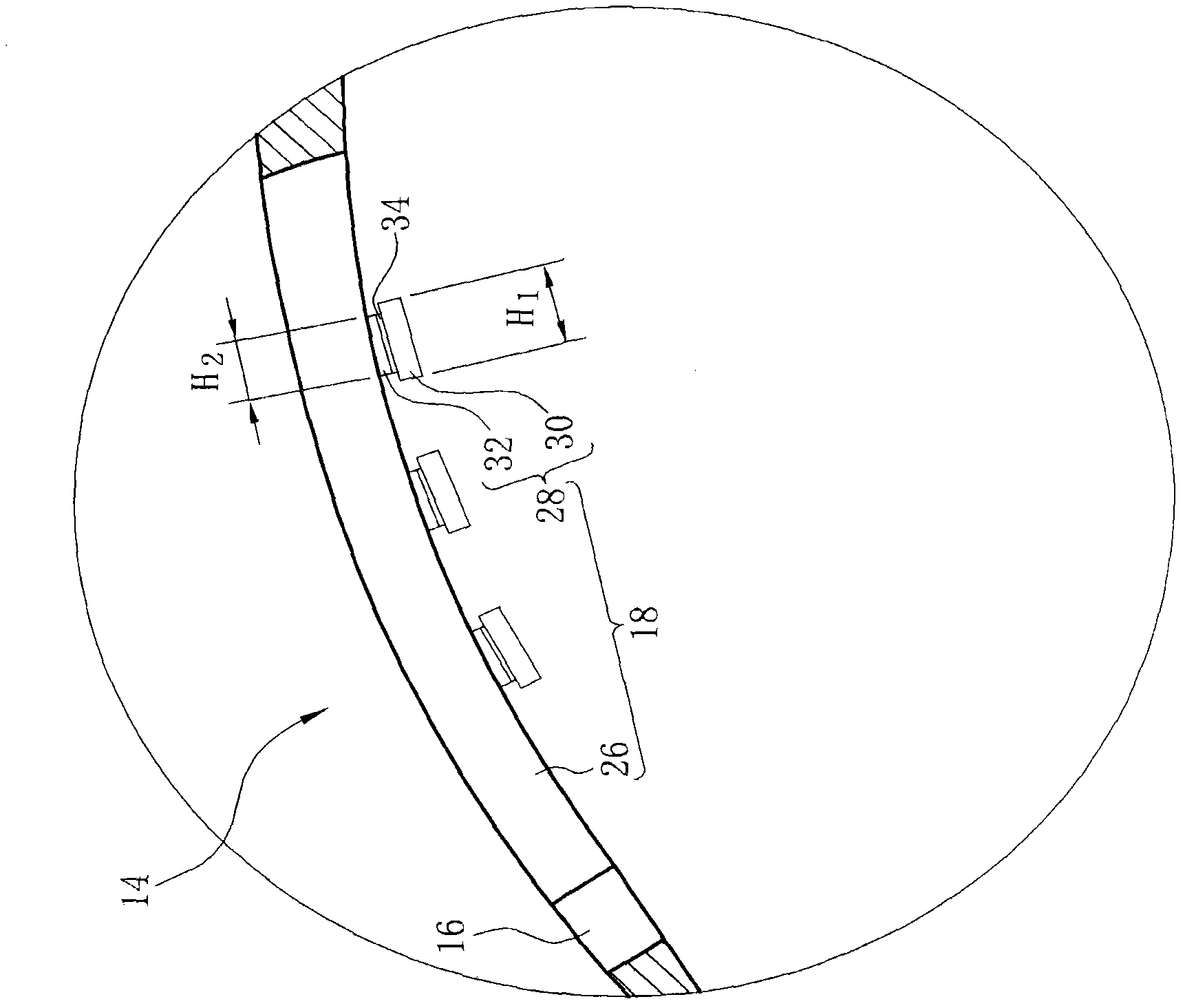
[0023] see figure 1 and figure 2 , figure 1 is a schematic diagram of an optical control device 10 according to an embodiment of the present invention, figure 2 It is a cross-sectional view of the structure of the light control device 10 according to the embodiment of the present invention. The light control device 10 may include a housing 12 and a light detection device 14 . The housing 12 is used to cover and protect multiple electronic components of the optical control device 10 , such as circuit boards, processors, transmission lines, and the like. The light detection device 14 is disposed on the surface of the housing 12 , and the user can use the light detection device 14 to control the operation of the electronic components inside the light control device 10 by utilizing the characteristics of light reflection and light shielding. The optical control device 10 can be an optical mouse, a touch panel, and the like.

[0024] The light detection device 14 includes a ...


PUM


Abstract

The invention discloses a light guide module which comprises a light guide board and a reflecting structure. The light guide board receives light front the lateral side to allow the light to be transmitted in the light guide board. The light guide board comprises a light emitting face and a bottom which are located on two different end faces of the light guide board. The reflecting structure is used for destroying total reflection of the light guide board to allow the light to be guided out of the light guide board. The reflecting structure comprises a first reflecting layer formed at the bottom of the light guide board and a second reflecting layer formed above the first reflecting layer. By the light guide module which can be used as a sensing component of a light sensing device, even backlight is provided, light spot interference caused by a reflecting light signal penetrating a plurality of light reflecting structures, and high sensing accuracy can be achieved.

Description

technical field [0001] The invention relates to a light guide module and its related light detection device, in particular to a light guide module and its related light detection device which reduce interference signals to improve detection accuracy. Background technique [0002] The light guide plate is a key component that acts as a light guiding medium in the backlight module. It can guide the direction of light when used in an edge-light backlight module to improve the brightness of the panel and control the uniformity of brightness. In the traditional side-type light guide plate, the light-emitting unit is placed on its side, and the light output from the light-emitting unit enters the light guide plate from the side and can be transmitted to the remote side of the light guide plate by using the principle of total reflection. The bottom surface of the light guide plate is printed with a plurality of reflective diffusion points, which can be used to break the total refle...

Claims


Application Information

Patent Timeline
Patent Type & Authority Applications(China)
IPC IPC(8): F21V13/02F21V7/22G06F3/033G06F3/042
Inventor 刘恬嘉陈晖暄
Owner PIXART IMAGING INC
Learn More