
Ratchet type tensioner

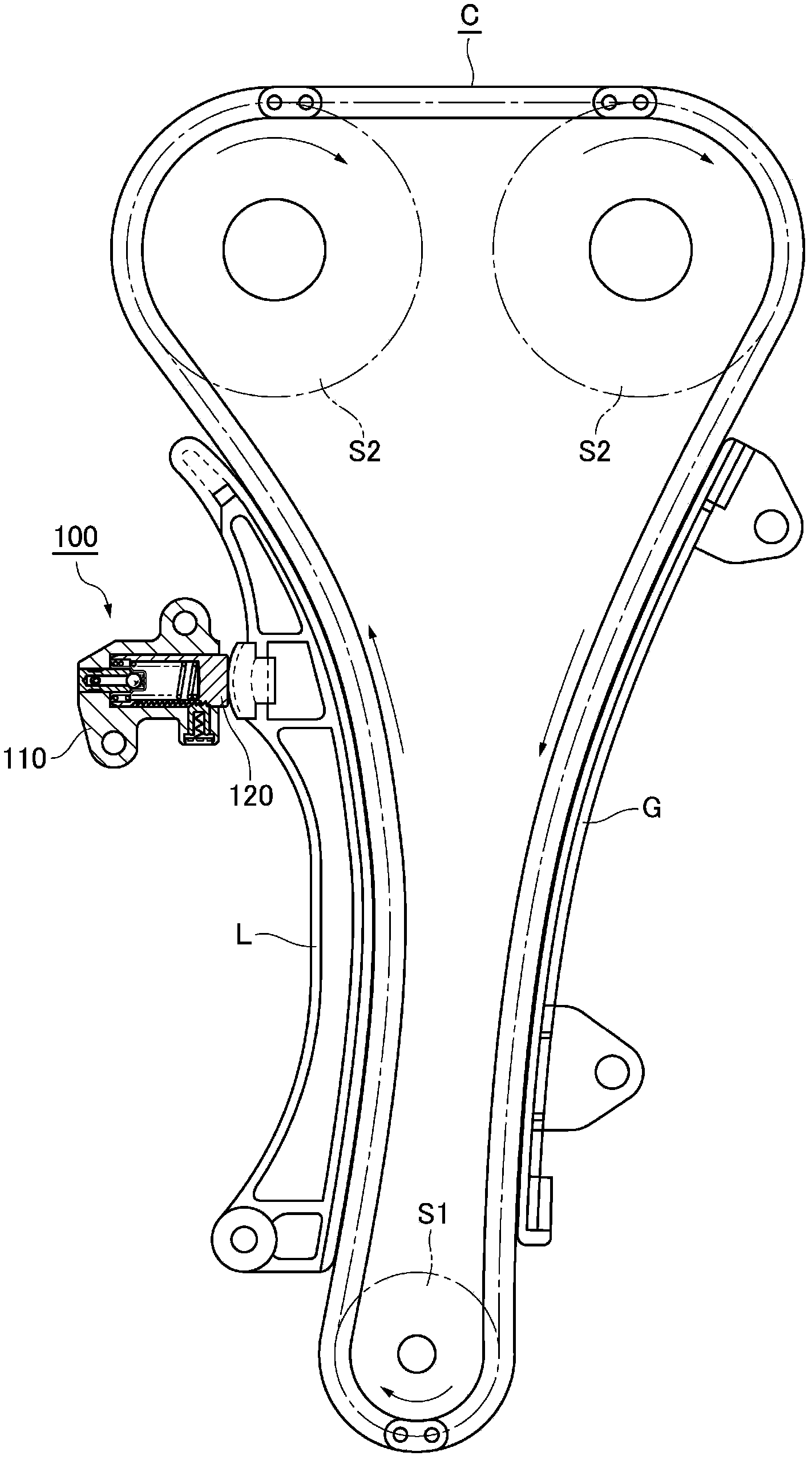
A tensioner and ratchet-type technology, applied in the direction of belts/chains/gears, mechanical equipment, transmission devices, etc., can solve the problems that the meshing teeth 536 are easy to be missing, misassembled, and meshing mismatches, etc., and achieve the effect of easy release

Inactive Publication Date: 2013-12-18
TSUBAKIMOTO CHAIN CO
View PDF7 Cites 0 Cited by
  • Summary
  • Abstract
  • Description
  • Claims
  • Application Information

AI Technical Summary

Problems solved by technology

[0008] Moreover, in the above-mentioned existing tensioner 500, since the plunger 514 and the piston 526 have a cylindrical structure, there is the following problem: the rack of the plunger 514 is damaged in response to the vibration of the plunger 514 when the engine is driven. 538 and the meshing teeth 536 of the piston 526 present an excessively locked state, and the meshing teeth 536 of the piston 526 are prone to lack of teeth, and soon distort throughout the entire area of ​​the tooth width and become meshing mismatches, resulting in The ratchet mechanism composed of the meshing teeth 536 and the rack 538 produces malfunctions; in addition, during the manufacture and maintenance of the tensioner, the plunger 514 and the piston 526 rotate around their respective axes, resulting in misassembly of each other

Method used


Image

  • Ratchet type tensioner
  • Ratchet type tensioner
  • Ratchet type tensioner

Examples


Embodiment Construction

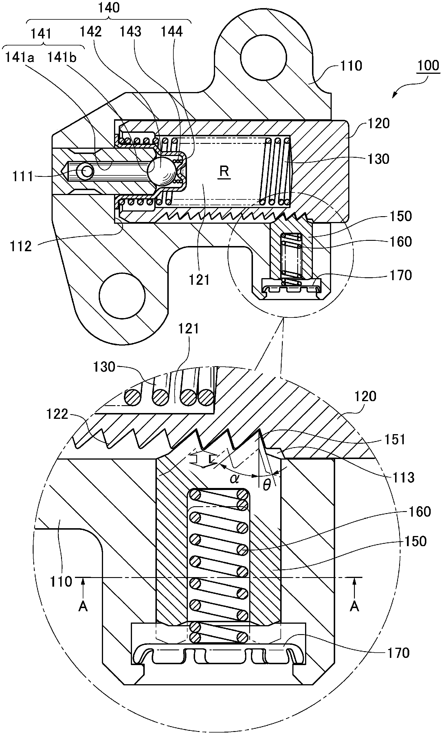
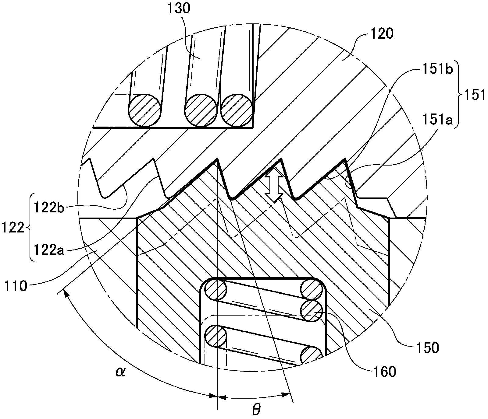
[0120] The ratchet type tensioner of the present invention includes: a housing body on which an oil supply passage for external pressure oil is formed; a plunger protruding freely from a plunger receiving hole of the housing body toward a traveling chain; In the high-pressure oil chamber formed between the plunger receiving hole of the housing main body and the hollow part of the plunger, force is applied along the protruding direction of the plunger; the cylindrical ratchet is inserted into the ratchet receiving hole of the housing main body, and Sliding in a direction perpendicular to the direction of advance and retreat of the plunger; the spring for ratchet loading loads the ratchet teeth provided at the front end area of ​​the plunger side of the ratchet toward the rack teeth on the side of the plunger; the spring lock plug , embedded near the rear end of the ratchet receiving hole and used for the ratchet to be loaded by a spring. The ratchet release mechanism uses a too...


PUM


Abstract

The invention provides a ratchet type tensioner. A ratchet mechanism comprising a plunger and a ratchet is simply and conveniently disengaged when the tensioner is maintained and repaired, the ratchet mechanism reliably and stably operates when an engine operates, malfunction is avoided, so that shaking sound is reduced, and hot sticking of the plunger is prevented. In the ratchet type tensioner (100), a ratchet removing mechanism for disengaging ratchet teeth (151) of the ratchet (150) from rack teeth (122) of the plunger (120) by a tool pin (T) comprises a tool pin clamping portion (154) and a pin inserting hole (114), the tool pin clamping portion (154) is arranged in a front end area of a plunger side of the ratchet (150) and used for abutting and clamping the front end (T1) of the tool pin (T), the pin inserting hole (114) is formed in a shell body (110) and faces the tool pin clamping portion (154), and the tool pin (T) is inserted into the pin inserting hole (114).

Description

technical field [0001] The present invention relates to a ratchet type tensioner that applies tension to a timing chain such as a camshaft that drives an engine. Background technique [0002] In the prior art, there is known a tensioner used for a timing chain that drives a camshaft of an engine, etc., which acts on a spring and a protruding force generated by external hydraulic pressure to slidably insert into a The plunger of the oil chamber is formed between the housing and the housing, thereby imparting tension to the timing chain. [0003] Such as Figure 16 As shown, as such a conventional tensioner, for example, a tensioner 500 having the following structure can be used. The tensioner 500 includes: a piston 526, which is slidably inserted into the housing 512 in a direction perpendicular to the sliding direction of the plunger 514, thereby forming an auxiliary oil chamber 520 with the housing 512; an oil passage 544, It is used to make the external hydraulic pressur...

Claims


Application Information

Patent Timeline
IPC IPC(8): F16H7/08
Inventor 吉田修榑松勇二前田宗裕石井彰
Owner TSUBAKIMOTO CHAIN CO
Learn More