
Automobile engine

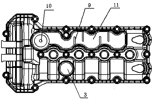
An automobile engine and engine technology, applied in the direction of engine components, machines/engines, mechanical equipment, etc., can solve problems such as engine failure, crankcase ventilation system failure, and engine performance, so as to reduce the risk of icing and avoid disadvantages impact, compact effect

Active Publication Date: 2013-12-18
CHONGQING CHANGAN AUTOMOBILE CO LTD
View PDF4 Cites 6 Cited by
  • Summary
  • Abstract
  • Description
  • Claims
  • Application Information

AI Technical Summary

Problems solved by technology

The automobile engine with this kind of cylinder head cover has the following problems: (1) During the small cycle of engine cold start, its temperature rises slowly. White deposits like cheese are often seen on the inner wall of the cover. The lower the temperature of the cylinder head cover, the more white deposits will be formed. Excessive white deposits will be attached to the fuel filler cap and inside, which will affect the engine oil. Thus affecting the performance of the engine; (2) The crankcase ventilation system of the engine separates the mixed gas that enters the crankcase from the piston ring, and separates the engine oil and water vapor. When the temperature is low in winter, if the temperature of the cylinder head cover If it is too low, water vapor will easily condense and freeze in the pipeline of the tortuous separation system, thereby blocking the pipeline and causing the crankcase ventilation system to fail, resulting in the engine not working normally

Method used


Image

  • Automobile engine
  • Automobile engine
  • Automobile engine

Examples


Embodiment Construction

[0012] The present invention will be further described below in conjunction with accompanying drawing.

[0013] Such as figure 1 , figure 2 The automobile engine shown comprises a cylinder head 8, a cylinder head cover 1, a thermostat seat 7 and an engine water inlet pipe 4, the cylinder head cover 1 is installed on the cylinder head 8, and the thermostat seat 7 is installed on one end of the cylinder head 8, The cylinder head cover 1 is a plastic part, which is provided with an oil filling port 3, a wave-shaped oil sump 11, a labyrinth cover plate 12 for sealing the oil sump, and a shape that is located on one side of the oil sump 11 and bends toward one end of the oil sump 11. The L-shaped water jacket 2, the oil filling port 3 is located at the outer end of the L-shaped bend of the water jacket 2, and is integrated with the water jacket 2, and several fins 9 are alternately arranged on the two side walls in the length direction of the oil collection tank. One end of the...


PUM


Abstract

The invention discloses an automobile engine. The automobile engine comprises a cylinder cover, a cylinder cover hood, a temperature adjuster seat and an engine water inlet pipe, wherein the cylinder cover hood is provided with an oil filling port, a wavy oil collecting groove and a water jacket; the water jacket is positioned at one side of the oil collecting groove, is bent towards one end of the oil collecting groove and is L-shaped; the water jacket is provided with a cooling-liquid inlet, a cooling-liquid outlet and a cooling-liquid flowing channel; the cooling-liquid inlet is connected with the temperature adjuster seat by the water inlet pipe; the cooling-liquid outlet is connected with the engine water inlet pipe by a water outlet pipe; the cooling-liquid flowing channel is formed by a water jacket partition and a water jacket inner wall, and the water jacket partition is positioned in the water jacket and is L-shaped; the cooling-liquid inlet and the cooling-liquid outlet are respectively positioned at the two ends of the cooling-liquid flowing channel; the oil filling port is positioned at the outer end of the L-shaped bending position of the water jacket and is integrally connected with the water jacket. The automobile engine disclosed by the invention has the advantages that during cold starting, the cylinder cover hood can heat and rise the temperature quickly, white attachments on the cylinder cover hood and the oil filling port cover can be reduced, and simultaneously the icing risk of a crankcase ventilating system is reduced.

Description

technical field [0001] The invention relates to automobile components, in particular to an automobile engine. Background technique [0002] The existing automobile engine comprises a cylinder head, a cylinder head cover, a thermostat seat and an engine water inlet pipe. The cylinder head cover is installed on the cylinder head, and the thermostat seat is installed on one end of the cylinder head. The engine water inlet pipe is connected as a coolant flow channel for the small circulation of the engine. The notification number is that a kind of cylinder head cover of engine is disclosed in the patent of CN202789181U, see image 3 , Figure 4 , including the cover body, the cover body is provided with a refueling port 3, a wave-shaped oil sump 11 and a labyrinth cover plate 12 for sealing the oil sump, and several fins are alternately arranged up and down on the two side walls in the length direction of the oil sump 9. One end of the oil collecting tank has an oil hole 10 co...

Claims


Application Information

Patent Timeline
Patent Type & Authority Applications(China)
IPC IPC(8): F02F7/00
Inventor 彭海赵勇付秋波郑素芳
Owner CHONGQING CHANGAN AUTOMOBILE CO LTD
Learn More