Double-shaft vacuum coating equipment for car lamp

A vacuum coating machine and car lamp technology, applied in vacuum evaporation coating, sputtering coating, ion implantation coating, etc., can solve the problem of increasing equipment cost and power configuration, increasing the production cycle of the furnace, reducing equipment utilization, etc. problems, to achieve the effect of reducing the time required for loading and unloading products, reducing logistics time and area occupied by logistics, and improving production efficiency

Active Publication Date: 2013-12-18
SHANGHAI HANA MECHANICAL & ELECTRICAL EQUIPMENT CO LTD
View PDF4 Cites 0 Cited by
  • Summary
  • Abstract
  • Description
  • Claims
  • Application Information

AI Technical Summary

Problems solved by technology

[0002] Traditional vacuum coating machines are mostly multi-pumping, such as 8-axis or 10-axis, because the number of axes is too large, and people are too late to hang parts. It seems that in many cases, there are machines waiting for people, and the equipment is heavy, which greatly reduces the utilization rate of the equipment. waste of energy
Although more parts can be installed due to the large number of shafts, the pumping speed is reduced, which increases the production cycle of the furnace. It also needs to be equipped with a larger pump, which increases the equipment cost and power configuration. It occupies a large area and the production capacity is changed from the traditional one. 15-25 points / furnace, increase to 8-12 points / furnace, also need to be equipped with other supporting equipment
In addition, the traditional type is a gear rotation structure, and the structure is heavy and often stuck

Method used


Image

  • Double-shaft vacuum coating equipment for car lamp
  • Double-shaft vacuum coating equipment for car lamp
  • Double-shaft vacuum coating equipment for car lamp

Examples


Embodiment Construction

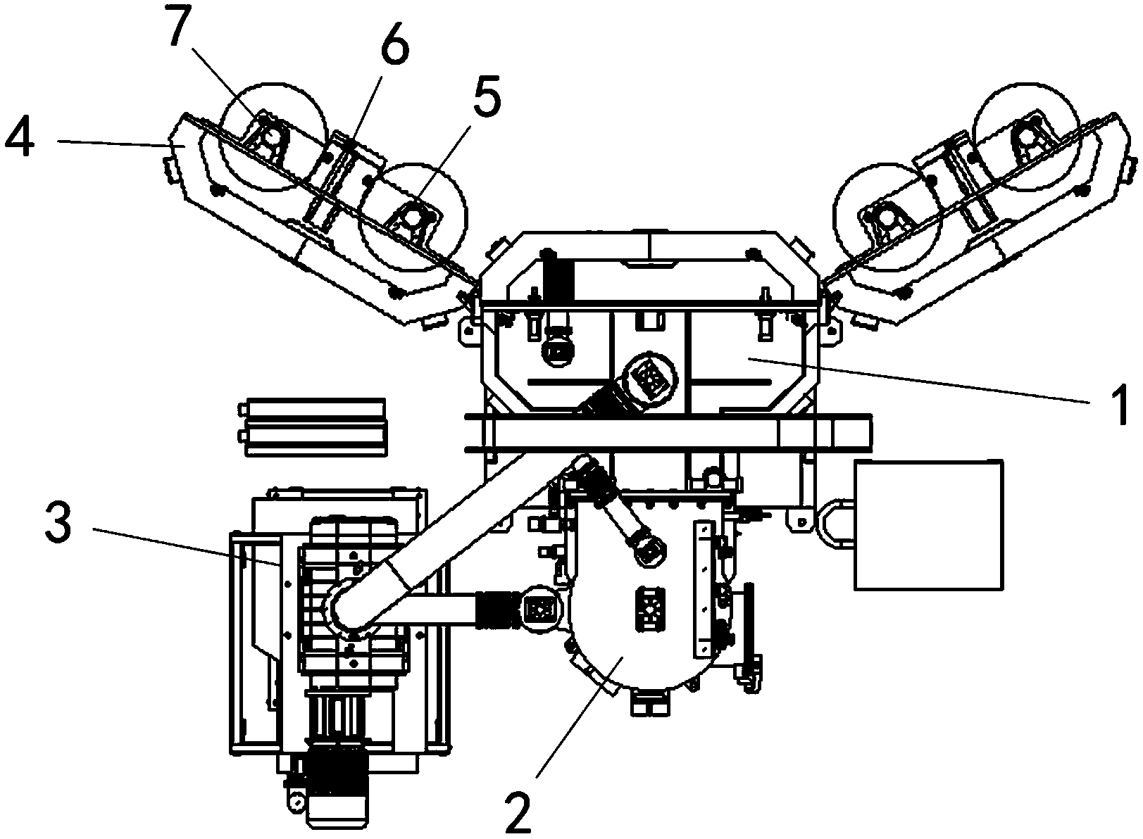
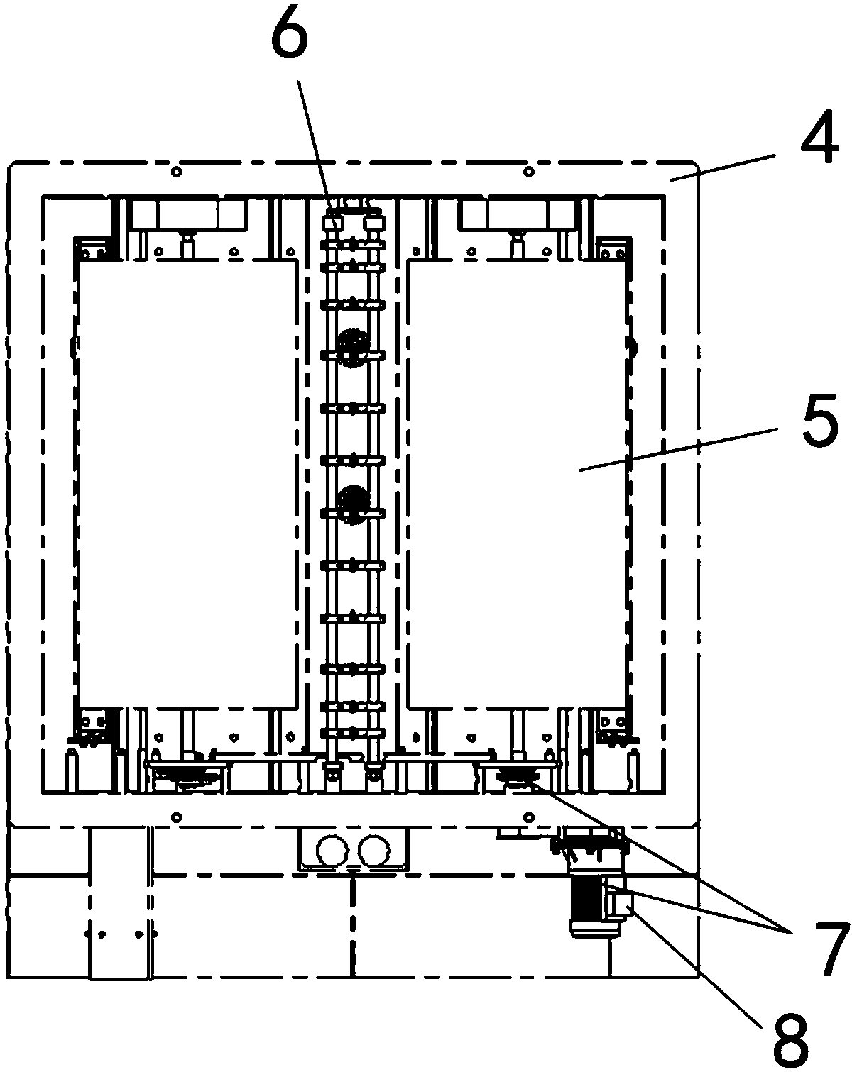
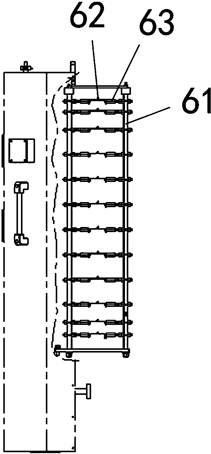
[0017] Such as Figure 1 to Figure 5 As shown, this specific embodiment adopts the following technical solutions: a double-axis car lamp vacuum coating machine, which includes a vacuum chamber cavity 1, a main valve cavity 2, and a pump unit 3, and the pump unit 3 is connected to the vacuum chamber cavity 1 and the main valve. Cavity 2, the vacuum chamber cavity 1 is provided with a pair of doors 4, the door 4 is hinged with the shell of the vacuum chamber cavity 1, and the inside of the door 4 is provided with a workpiece fixture 5, an evaporative device 6 and a rotating device 7, The evapotranspiration device 6 is arranged in the middle part of the inner side of the door, and the evapotranspiration device 6 is composed of a bracket 61, on which an evapotranspiration unit is arranged, and the evapotranspiration unit is formed by connecting an evaporative tungsten wire 62 and an evaporative copper rod 63; the rotating device 7 includes a motor 71, Synchronous pulley 72, magnet...


PUM


Abstract

The invention discloses double-shaft vacuum coating equipment for a car lamp. The double-shaft vacuum coating equipment is characterized by comprising a vacuum chamber cavity, a main valve cavity and a pump set, wherein the pump set is connected with the vacuum chamber cavity and the main valve cavity, a pair of doors is arranged on the vacuum chamber cavity and hinged with a housing of the vacuum chamber cavity, a workpiece clamp, an evapotranspiring device and a rotating device are arranged at the inner side of each door; the evapotranspiring device is arranged at the middle of the inner side of each door and comprises a bracket, wherein an evapotranspiring unit is arranged on the bracket, and the evapotranspiring unit is formed by connecting an evapotranspiring tungsten filament and an evapotranspiring copper rod. The double-shaft vacuum coating equipment has the beneficial effects that the weight of the whole equipment is greatly reduced, the equipment only rotates, each door is controlled by a single frequency converter, the revolution of shafts can be regulated at any time, the structure is simple, convenience is brought for maintenance, the weight of each door is integrally reduced so that the door is more easily opened in a labor-saving manner, and the evapotranspiring rods are arranged between the two shafts so that paint can be more fully evapotranspired to a product and the pollution to the inner wall is reduced.

Description

technical field [0001] The invention relates to a double-axis vehicle lamp vacuum coating machine, which belongs to the technical field of vacuum coating machines. Background technique [0002] Traditional vacuum coating machines are mostly multi-pumping, such as 8-axis or 10-axis, because the number of axes is too large, and people are too late to hang parts. It seems that in many cases, there are machines waiting for people, and the equipment is heavy, which greatly reduces the utilization rate of the equipment. Waste of energy. Although more parts can be installed due to the large number of shafts, the pumping speed is reduced, which increases the production cycle of the furnace. It also needs to be equipped with a larger pump, which increases the equipment cost and power configuration. It occupies a large area and the production capacity is changed from the traditional one. 15-25 points / furnace, if it is increased to 8-12 points / furnace, it also needs to be equipped wi...

Claims


Application Information

Patent Timeline
IPC IPC(8): C23C14/24C23C14/50
Inventor 夏伟李龙哲沈聚丰周征华金虎
Owner SHANGHAI HANA MECHANICAL & ELECTRICAL EQUIPMENT CO LTD
Why Eureka
Try Eureka