
Material fluidization pressurization tube device

A pressurized tube, fluidized technology, used in the transportation of bulk materials, transportation and packaging, conveyors, etc., can solve problems such as increased transportation resistance, deterioration, and reduced material flow area.

Inactive Publication Date: 2013-12-18
YUNNAN HUAYUN TIANLANG ENVIRONMENTAL PROTECTION
View PDF7 Cites 4 Cited by
  • Summary
  • Abstract
  • Description
  • Claims
  • Application Information

AI Technical Summary

Problems solved by technology

[0002] At present, the existing material conveying devices often block the pipeline due to conventional pneumatic conveying. At the same time, sticky particles are easy to adhere to the inner wall of the pipeline. Under the condition of external temperature and humidity changes, a material cake is formed, which affects the material performance and even deteriorates. clogged pipes or valves
The material bonded to the inner wall of the horizontal pipe will form material scale for a long time, resulting in a decrease in the material flow area and an increase in the conveying resistance

Method used


Image

  • Material fluidization pressurization tube device
  • Material fluidization pressurization tube device
  • Material fluidization pressurization tube device

Examples


Embodiment approach 1

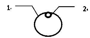
[0019] A material fluidization sending device is installed at the lower part of the sintering flue gas desulfurization device in the iron and steel plant, and then the material fluidization sending device is connected with the material fluidization pressure pipe device. A material fluidization pressure pipe device consists of two sets Tube composition, conveying material fluidization large pipe 1 and double casing inner pipe 2, the connection relationship is that the upper part of the conveying material fluidization large pipe 1 is equipped with double casing inner pipe 2.

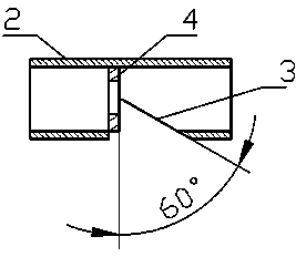
[0020] The inside of the double casing inner tube 2 is equipped with throttling orifice plates 4 equidistantly and uniformly.

[0021] The said throttling orifice plate 4 is welded to the inner wall of the double sleeve inner tube 2 .

[0022] The material of the throttle orifice 4 is 16Mn.

[0023] The rear of the throttling orifice plate 4 of the tube wall of the double-sleeve inner tube 2 is equally sp...


PUM


Abstract

The invention relates to a material fluidization pressurization tube device which consists of double sleeves: a conveyed material fluidized big pipe and a double-sleeve inner pipe. The conveyed material fluidized big pipe and the double-sleeve inner pipe are in a connection relation that the double-sleeve inner pipe is arranged in the conveyed material fluidized big pipe; throttling orifices are uniformly arranged at equal intervals inside the double-sleeve inner pipe; and double-sleeve inner pipe; through holes are uniformly formed at equal intervals in the rear parts of the throttling orifices on the pipe wall of the double-sleeve inner pipe. The material fluidization pressurization tube device can be widely applied to the field of material fluidization sending.

Description

technical field [0001] The invention belongs to a material conveying device, in particular to a device for pressurized fluidized delivery of materials. Background technique [0002] At present, the existing material conveying devices often block the pipeline due to conventional pneumatic conveying. At the same time, sticky particles are easy to adhere to the inner wall of the pipeline. Under the condition of external temperature and humidity changes, a material cake is formed, which affects the material performance and even deteriorates. Blockage of pipes or valves. The material sticking to the inner wall of the horizontal pipe will form material scale for a long time, resulting in a decrease in the material flow area and an increase in the conveying resistance. In particular, materials with certain characteristics, such as by-products of dry calcium desulfurization, will stay in the pipeline for a long time and will corrode the pipeline and valves. It is necessary to inv...

Claims


Application Information

Patent Timeline
IPC IPC(8): B65G53/66
Inventor 李跃春潘凡李彩伦李忠林周洲
Owner YUNNAN HUAYUN TIANLANG ENVIRONMENTAL PROTECTION
Learn More