Eureka AIR delivers breakthrough ideas for toughest innovation challenges, trusted by R&D personnel around the world.

Material fluidization sending method

A fluidization and material technology, applied in the direction of containers, packaging, transportation and packaging, etc., can solve problems such as deterioration, increase in conveying resistance, and affect material performance

Active Publication Date: 2013-12-18
YUNNAN HUAYUN TIANLANG ENVIRONMENTAL PROTECTION
View PDF4 Cites 0 Cited by
  • Summary
  • Abstract
  • Description
  • Claims
  • Application Information

AI Technical Summary

Problems solved by technology

[0002] At present, the existing material conveying devices often block the pipeline due to conventional pneumatic conveying. At the same time, sticky particles are easy to adhere to the inner wall of the pipeline. Under the condition of external temperature and humidity changes, a material cake is formed, which affects the material performance and even deteriorates. clogged pipes or valves
The material bonded to the inner wall of the horizontal pipe will form material scale for a long time, resulting in a decrease in the material flow area and an increase in the conveying resistance

Method used


Image

  • Material fluidization sending method
  • Material fluidization sending method
  • Material fluidization sending method

Examples


Embodiment approach 1

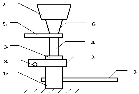
[0022] In the lower part of the sintering flue gas desulfurization device, a method of material fluidization delivery is implemented, and a material fluidization delivery device is installed, which consists of a waste slag bucket 7 at the bottom of the tower, a variable diameter joint 6, a knife gate valve 5, a pipeline 4, and a waveform Compensator 3, double gate feed valve 2, and sender 1. The connection relationship is: the bottom of the waste slag hopper 7 at the bottom of the tower is connected to the upper part of the variable diameter joint 6, and the lower part of the variable diameter joint 6 is connected to the inlet of the knife gate valve 5. , the outlet of the knife-shaped gate valve 5 is connected to the inlet of the pipeline 4, the outlet of the pipeline 4 is connected to the upper part of the wave compensator 3, the lower part of the wave compensator 3 is connected to the inlet of the double ram feed valve 2, and the double ram feed The outlet of the valve 2 is ...

Embodiment approach 2

[0035] In the step (2), when the main ash conveying pipeline has a bend in the conveying process, adjust the internal pressure of the main ash conveying pipeline to ≥0.3Mpa.

[0036] The remaining steps are the same as above and will not be repeated.


PUM

PropertyMeasurementUnit
Sizeaaaaaaaaaa

Abstract

The invention relates to a material fluidization sending method which comprises the following operation steps that a compressed air source is opened; when an air pressure inside a sender reaches 0.4Mpa, a pressure in a main ash conveying pipeline reaches 0.2Mpa and a pressure in a double-sleeve inner pipeline reaches 0.2Mpa, a manual knife-shaped gate valve is opened, so that ash freely falls down from a waste slag ash hopper; and a double-gate feed valve is opened, so that the ash enters the sender and the ash is conveyed out along the main ash conveying pipeline by the transverse air pressure. The material fluidization sending method can be widely applied to the field of material fluidization sending.

Description

technical field [0001] The patent of the present invention belongs to a material conveying device, and in particular relates to a method for pressurized fluidized delivery of materials. Background technique [0002] At present, the existing material conveying devices often block the pipeline due to conventional pneumatic conveying. At the same time, sticky particles are easy to adhere to the inner wall of the pipeline. Under the condition of external temperature and humidity changes, a material cake is formed, which affects the material performance and even deteriorates. Blockage of pipes or valves. The material sticking to the inner wall of the horizontal pipe will form material scale for a long time, resulting in a decrease in the material flow area and an increase in the conveying resistance. In particular, materials with certain characteristics, such as by-products of dry calcium desulfurization, will stay in the pipeline for a long time and will corrode the pipeline a...

Claims


Application Information

Patent Timeline
IPC IPC(8): B65D88/72
Inventor 潘凡李跃春李彩伦矣震东郭隆
Owner YUNNAN HUAYUN TIANLANG ENVIRONMENTAL PROTECTION
Why Eureka
Eureka Blog
Learn More