
Vehicle auxiliary drive mechanism

A vehicle and engine technology, applied to vehicle parts, brake components, brakes, etc., can solve the problems that the braking energy of fuel vehicles is directly used to drive the vehicle, and the fuel consumption of the engine cannot be significantly reduced

Inactive Publication Date: 2013-12-18
ZHEJIANG JINGANG AUTOMOBILE +1
View PDF6 Cites 5 Cited by
  • Summary
  • Abstract
  • Description
  • Claims
  • Application Information

AI Technical Summary

Problems solved by technology

[0008] The object of the present invention is to provide a fuel-fueled vehicle that can be used to drive the vehicle to overcome the problems that the existing vehicle auxiliary drive device cannot significantly reduce the fuel consumption of the engine and that the braking energy cannot be directly used to drive the vehicle on the fuel vehicle. Vehicle drive-assisting mechanism and method for directly absorbing and storing braking energy during driving and using it to drive the vehicle to start

Method used


Image

  • Vehicle auxiliary drive mechanism
  • Vehicle auxiliary drive mechanism
  • Vehicle auxiliary drive mechanism

Examples


Embodiment Construction

[0030] The present invention will be further described below in conjunction with the accompanying drawings and specific embodiments.

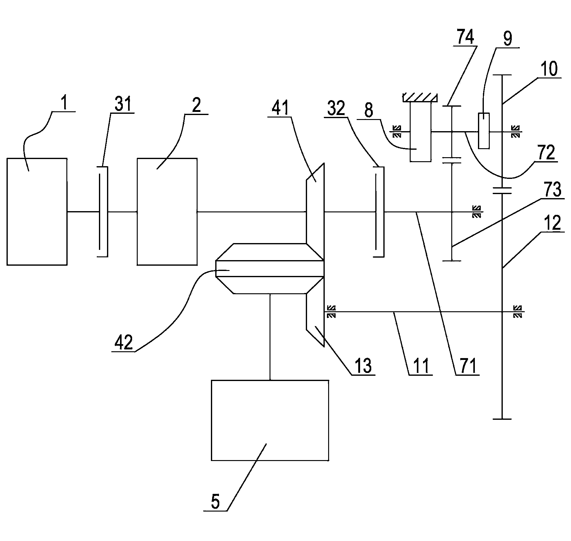
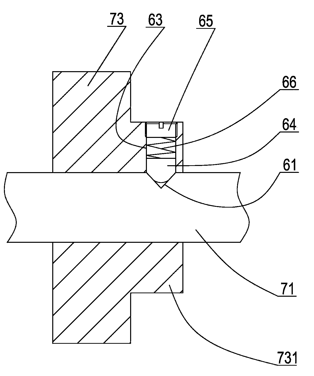
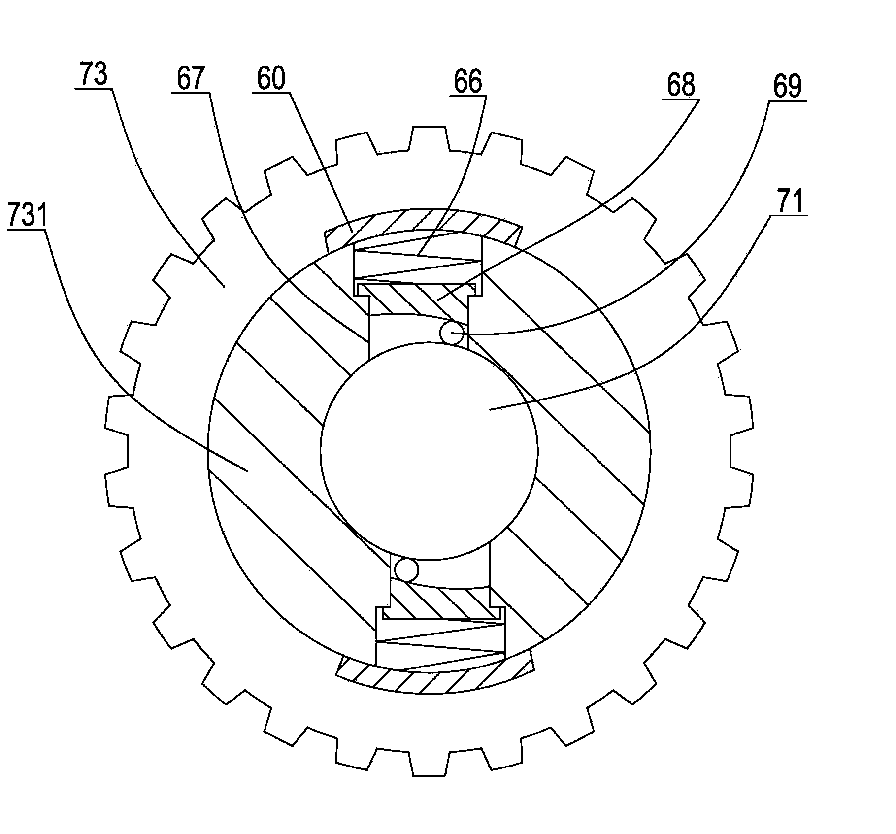
[0031] Such as figure 1 As shown, a vehicle drive assist mechanism of the present invention includes an engine 1, a transmission 2, and a first clutch 31 connected between the engine and the transmission. The output end of the transmission is connected to the differential 5 through a reduction gear set. The reduction gear set includes a driving bevel gear 41 arranged at the output end of the transmission, and a double-sided driven bevel gear 42 connected to the differential. The driving bevel gear meshes with one side of the double-sided driven bevel gear. When the vehicle is running normally, the first clutch is engaged, and the power of the engine is transmitted to the transmission through the first clutch. After the transmission is shifted, it is output from the output end, and then transmitted to the differential through the active bevel ge...


PUM


Abstract

The invention discloses a vehicle auxiliary drive mechanism which comprises an engine, a transmission, a first clutch, a vehicle speed sensor and a controller. The first clutch is connected between the engine and the transmission. An output end of the transmission is connected with a differential mechanism through a reduction gear set. A position sensor is disposed on the first clutch. The output end of the transmission is connected with an input shaft of an accumulation transmission system through a second clutch which is connected with a brake pedal. An output shaft of the accumulation transmission system is provided with an accumulation coil spring and a locking device. The output shaft of the accumulation transmission system is connected with the differential mechanism through an auxiliary drive transmission system which can transmit power unidirectionally. The vehicle speed sensor and the position sensor are connected with an input end of the controller. An output end of the controller is connected with the locking device. By the vehicle auxiliary drive mechanism, brake energy during traveling of fuel vehicles can be fully absorbed, stored and used for driving vehicle starting, starting performance of the vehicles can be improved favorably, and oil consumption and emission can be lowered evidently.

Description

[0001] technical field [0002] The invention relates to an auxiliary driving device for a vehicle, in particular to a vehicle driving auxiliary mechanism which can store vehicle braking energy and use it for auxiliary driving when starting, and a corresponding driving auxiliary method. [0003] Background technique [0004] Vehicles need frequent braking and starting during driving. Existing vehicle braking is usually achieved by hydraulically driven brake calipers clamping brake pads that are coaxial with the wheel shaft. Since the brakes rely on brake calipers The friction between the brake disc and the brake disc is completed. Therefore, frequent braking will cause the wear of the brake calipers and brake discs and other braking devices, which need to be replaced after a period of use, and the inertial kinetic energy of the vehicle during the braking process is lost Convert it into heat energy and waste it in vain. In addition, when the vehicle is restarted after braki...

Claims


Application Information

Patent Timeline
Patent Type & Authority Applications(China)
IPC IPC(8): B60T1/10
Inventor 管军荣顾伟明
Owner ZHEJIANG JINGANG AUTOMOBILE
Learn More