
Cable pulling device

A technology of wire pulling device and wire pulling reel, which is applied in the direction of cable laying equipment, etc., can solve problems such as difficult operation and messy cables, and achieve the effect of increasing the effect

Active Publication Date: 2015-02-11
CHONGQING RUIPU CABLE
View PDF5 Cites 5 Cited by
  • Summary
  • Abstract
  • Description
  • Claims
  • Application Information

AI Technical Summary

Problems solved by technology

[0003] The technical problem to be solved by the present invention is to provide a cable that is not easy to mess up when pulling the wire in the cable groove and easy to operate when the cable is connected to the equipment, aiming at the current technical defects that the cable is easy to be confused when pulling the wire in the cable groove and the cable is not easy to operate when connecting the equipment. Operated pull device

Method used


Image

  • Cable pulling device
  • Cable pulling device
  • Cable pulling device

Examples


Embodiment Construction

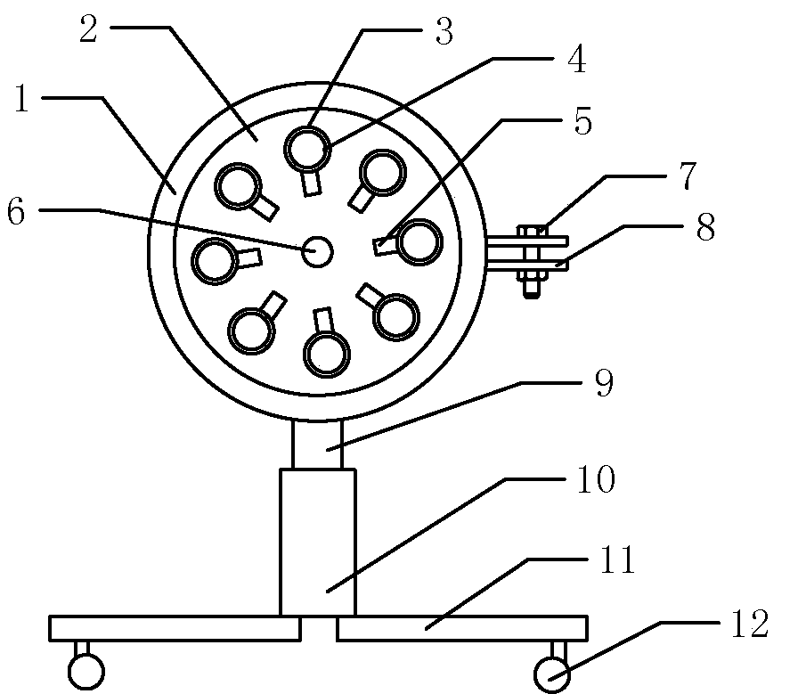
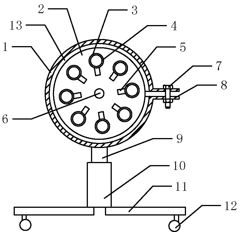
[0015] Among them, fixed ring 1, cable reel 2, cable hole 3, cable tie 4, label plate 5, hanging ring 6, locking bolt 7, locking block 8, support rod 9, fixing sleeve 10, foot 11, roller 12 , Card slot 13.

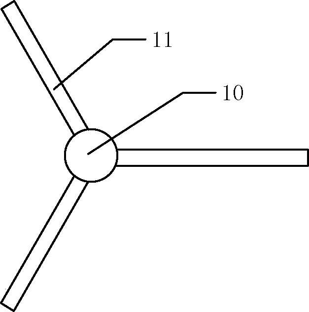
[0016] Such as figure 1 , 2 As shown, the wire pulling device of the present invention includes a fixing device and a wire reel 2, the fixing device includes a fixing frame and a fixing ring 1, the fixing frame includes a base and a support rod 9, and the base includes a fixing sleeve 10 and three legs 11. The lower ends of the three legs 11 have rollers 12, and the three legs 11 are fixedly connected to the lower end of the fixed sleeve 10, and the three legs 11 are evenly distributed around the fixed sleeve 10, as image 3 As shown, there is a threaded hole in the center of the upper end of the fixing sleeve 10, and the support rod 9 is threadedly connected with the fixing sleeve 10 through the threaded hole. There are locking blocks 8 on both sides of the gap of the ...


PUM


Abstract

The invention discloses a cable pulling device, which comprises a fixing device and a cable pulling disc, wherein the fixing device comprises a fixing frame and a fixing ring, the fixing frame comprises a base and a support rod, the support rod is positioned at the center of the base, and is connected with the base by thread, the fixing ring is fixedly connected with the upper end of the support rod, the fixing ring is in a circle shape and is provided with a notch, locking blocks are respectively arranged at the two sides of the notch of the fixing ring, a locking bolt is arranged between the two locking blocks, the fixing ring is provided with a clamping groove along the circumferential direction, and is an elastic clamping groove, the cable pulling disc is positioned in the clamping groove and is abutted against the clamping groove, a group of cable pulling holes are formed in the cable pulling disc, a binding belt is arranged in the inner wall of each cable pulling hole, and a hanging ring is arranged at the center of the cable pulling disc. The cable pulling device overcomes the technical defects of disordering of cables and difficult operation of cable connecting equipment in the cable pulling process in a cable tray, and has the advantages that the disordering of the cables is avoided and the operation of the cable connecting equipment is easy when the cable is pulled in the cable tray.

Description

technical field [0001] The invention belongs to the field of cables, and in particular relates to a wire pulling device. Background technique [0002] In factories, cables are usually used to connect equipment, so that equipment can be connected with each other, such as the connection between production equipment and control cabinets; in order to prevent cables from being damaged by foreign objects, cable troughs are usually set up under the ground When installing the equipment, place the cables in the cable trough to avoid damage to the cables by foreign objects. The cable trough is usually in the shape of a through hole. After placing the cables in the cable trough, seal the end of the cable trough with a steel plate; In practical applications, multiple cables are usually used for the connection between devices, and in order to save the cost of setting up cable trays, multiple cables of multiple devices are usually placed in one cable tray. When connecting cables for new ...

Claims


Application Information

Patent Timeline
Patent Type & Authority Applications(China)
IPC IPC(8): H02G1/08
Inventor 王云
Owner CHONGQING RUIPU CABLE
Learn More