
Acoustic velocity correction method for photoacoustic imaging

A photoacoustic imaging and sound velocity technology, which is applied in image data processing, 2D image generation, medical science, etc.

Inactive Publication Date: 2013-12-18
NANJING UNIV
View PDF5 Cites 9 Cited by
  • Summary
  • Abstract
  • Description
  • Claims
  • Application Information

AI Technical Summary

Problems solved by technology

[0004] Purpose of the invention: the technical problem to be solved by the present invention is the problem of inaccurate sound velocity in a quasi-homogeneous medium. For the problem of photoacoustic reconstruction that cannot test the sound velocity, different curve equations are fitted through the selection of finite subsonic velocity and delay compensation. Solve to obtain more accurate sound velocity, so as to reconstruct a higher quality image

Method used


Image

  • Acoustic velocity correction method for photoacoustic imaging
  • Acoustic velocity correction method for photoacoustic imaging
  • Acoustic velocity correction method for photoacoustic imaging

Examples


Embodiment Construction

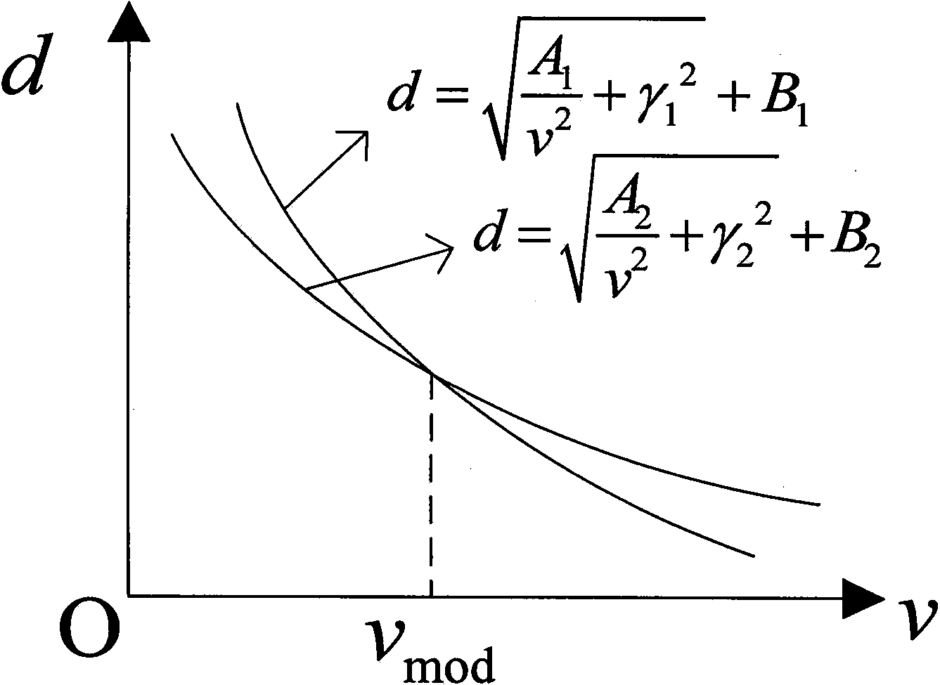
[0029] The present invention combines the time-delay summation algorithm to fit the relationship curves of the focused sound velocity and delay compensation for different imaging targets, and then solve the corrected sound velocity by combining these relationship curves.

[0030] like figure 1 As shown, the present invention discloses a method for correcting sound velocity in photoacoustic imaging, which includes the following steps:

[0031] In step 1, a laser is used to emit laser light in a photoacoustic imaging device system.

[0032] Step 2, the line sensor receives the ultrasonic signal.

[0033] Step 3, formulate focus evaluation criteria and select the focus position for reconstruction.

[0034] Step 4, calculate the pixel size, and realize the fixation of the pixel position of the reconstructed image.

[0035] Step 5: Reconstruct the image with the time-delayed summation method.

[0036] Step 6, adjust the sound velocity and delay compensation, realize the separat...


PUM


Abstract

The invention discloses an acoustic velocity correction method for photoacoustic imaging. The method includes the steps of irradiating tissue under test by laser in a photoacoustic imaging system; using a linear sensor to acquire ultrasonic signals emitted by the irradiated tissue; determining a focus evaluation standard, and selecting a focus position; adjusting the acoustic velocity and delay compensation, rebuilding an image by means of delay and sum process, and focusing a selected point; fitting curves of relation between the acoustic velocity and delay compensation according to the relation between the acoustic velocity and delay, and determining curve parameters; performing simultaneous solution on the curves of relation of different focus depths to obtain the corrected acoustic velocity and delay compensation. The linear sensor is used for acquiring signals; the image is rebuilt by means of delay and sum process; a relation equation for the focused acoustic velocity and delay compensation is obtained by adjusting the target acoustic velocities and delay compensations of different positions; the corrected acoustic velocity is acquired by a simultaneous equation; accordingly, operation is simple.

Description

technical field [0001] The invention relates to the field of image reconstruction of photoacoustic imaging, in particular to a method for correcting sound velocity in photoacoustic imaging. Background technique [0002] Photoacoustic imaging is a non-destructive medical imaging method developed in recent years, which can provide high-resolution and high-contrast tissue imaging. It is a non-destructive biophoton imaging method based on the difference in optical absorption inside biological tissues and using ultrasound as a medium. It combines the advantages of high contrast characteristics of pure optical imaging and high penetration depth characteristics of pure ultrasound imaging. Photoacoustic waves replace photon detection in optical imaging, avoiding the influence of optical scattering in principle, and can provide high-contrast and high-resolution tissue images. It provides an important means and has broad application prospects in the fields of biomedical clinical diag...

Claims


Application Information

Patent Timeline
Patent Type & Authority Applications(China)
IPC IPC(8): A61B5/00G06T11/00
Inventor 袁杰李文超夏煦菁张星封婷邵真天朱毅温馨储哲琪顾鹏沈庆宏都思丹
Owner NANJING UNIV
Learn More