
Vending machine

A technology for vending machines and mobile mechanisms, which is applied to instruments, coin-operated equipment for distributing discrete items, and coin-operated equipment for distributing discrete items, etc., can solve the problem of increased manufacturing costs, reduced workability, and increased installation space. big problem

Active Publication Date: 2013-12-11
SANDEN RETAIL SYST CORP
View PDF5 Cites 4 Cited by
  • Summary
  • Abstract
  • Description
  • Claims
  • Application Information

AI Technical Summary

Problems solved by technology

[0006] For this reason, when the energization to the motor is stopped due to abnormality detection, if the commodity receiver is locked and does not move in the vertical direction, the free fall of the commodity receiver can be prevented, but if the commodity receiver is locked, Then, in the maintenance work for resale, it is not possible to manually move the product receiver, and there is a problem that the workability is reduced.
However, if the product receiver is unlocked, the product receiver will fall freely, so there is a problem that the product receiver will fall if the product receiver is not supported.
[0007] Moreover, if a counterweight is provided to balance the product receiver, the product receiver will not fall freely even if the energization toward the motor is stopped. Problems of increase in manufacturing cost and increase in installation space
Furthermore, setting a counterweight balanced with the product receiver allows the product receiver to fall freely due to the weight of the product when the product straddles the product receiver, so there is also a problem that the product receiver cannot be reliably prevented from falling.
[0008] The present invention has been made in view of the above problems, and its object is to provide an automatic vending machine that does not cause damage to the product receiver or damage to the product due to the impact of the drop even when the product receiver falls freely. Fly out without complicated structure to prevent free fall of product receiver

Method used


Image

  • Vending machine
  • Vending machine
  • Vending machine

Examples


Embodiment Construction

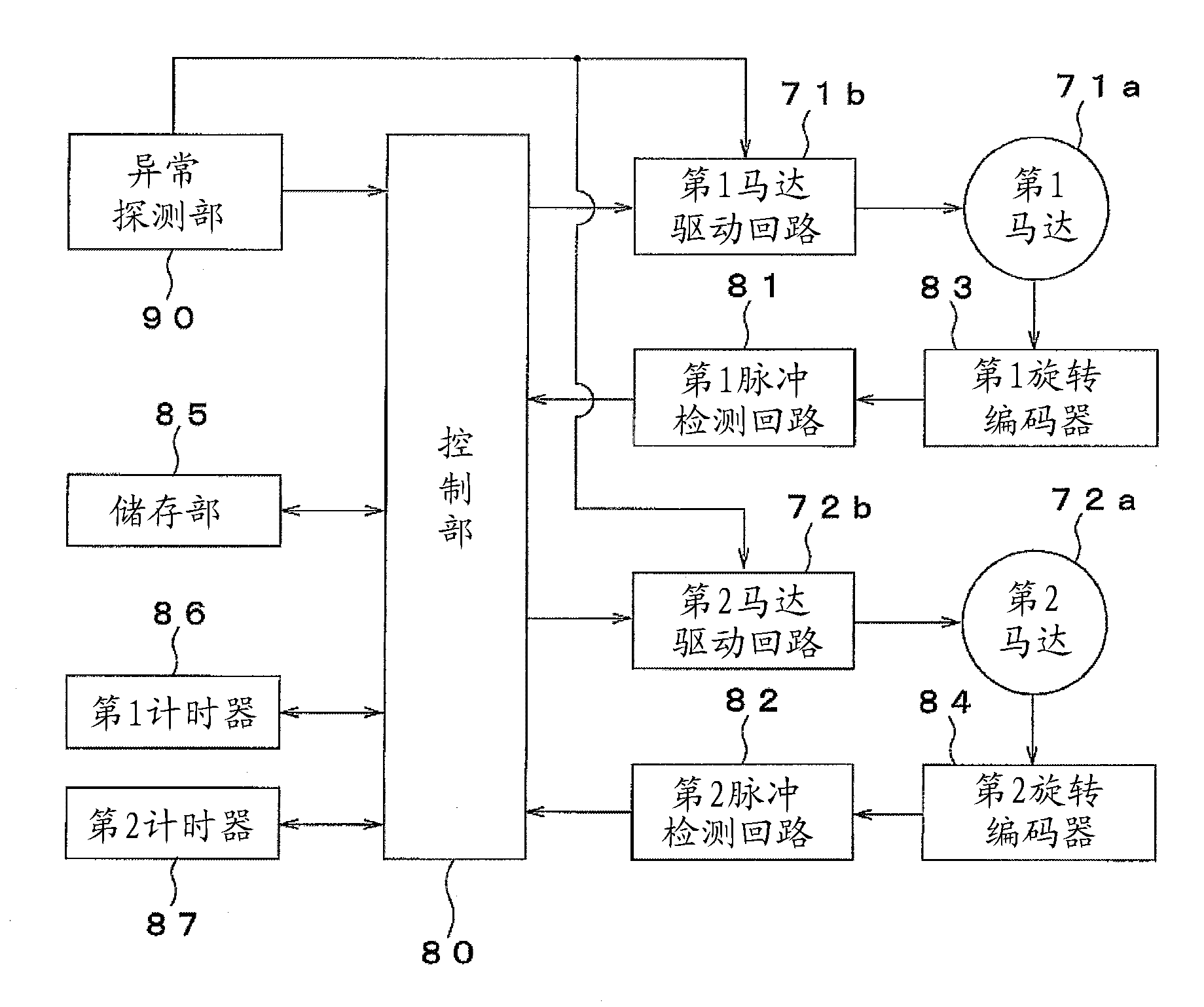
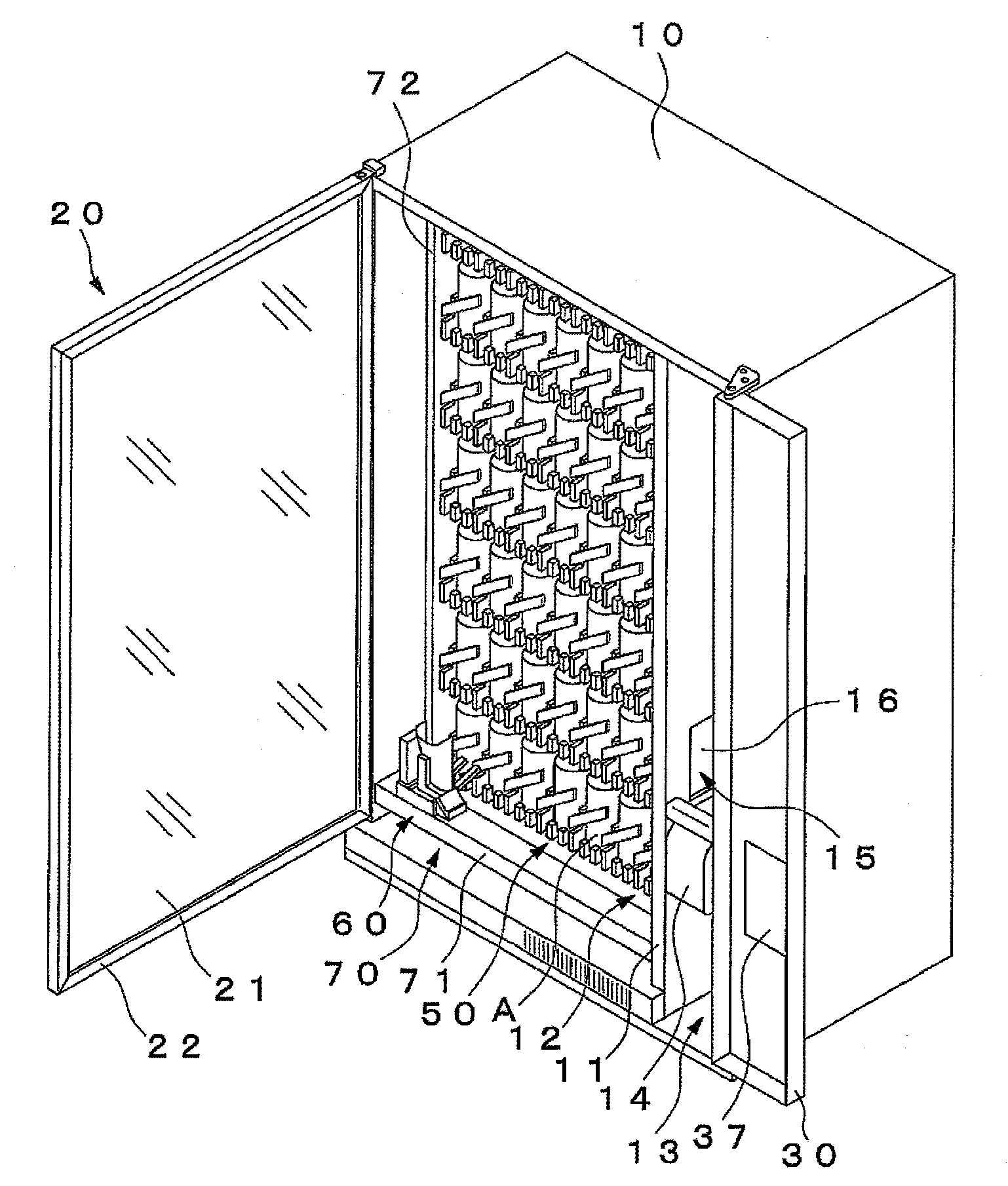
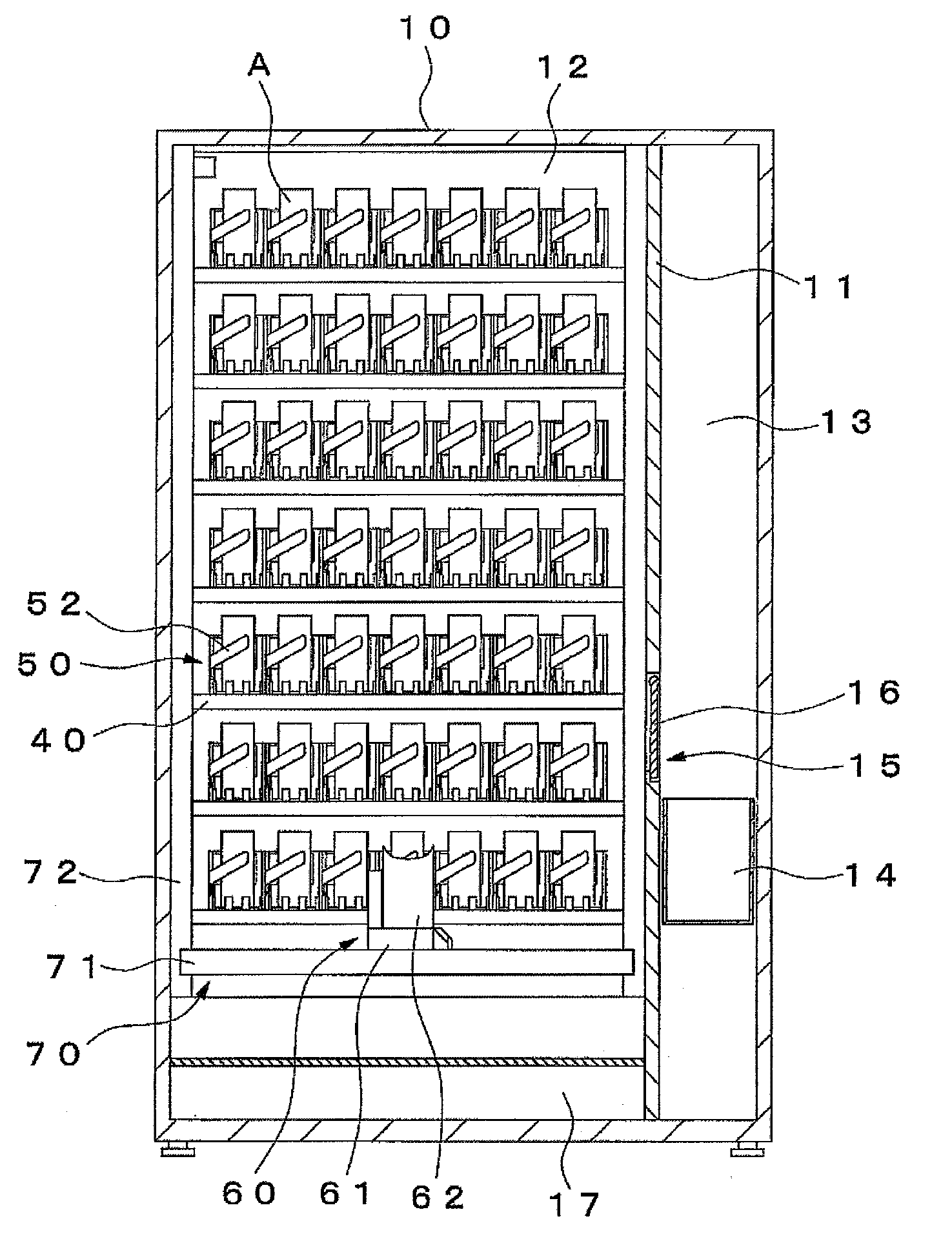
[0021] Figure 1 to Figure 6 An embodiment of the present invention is shown. This automatic vending machine is provided with: the automatic vending machine main body 10 of opening front surface, the outer door 20 of opening and closing the width direction one end side of the opening portion of the automatic vending machine main body 10 , and the width direction of the opening portion of the automatic vending machine main body 10 . The operation door 30 on the other end side.

[0022] The main body 10 of the automatic vending machine has a commodity storage 12 for accommodating commodities A for sale, and a machine storage 13 for accommodating machines for selling. spaced across the width. A product take-out unit 14 from which the product A is delivered is provided at a lower portion of the machine storage 13 , and an opening 15 connecting the product take-out unit 14 and the product storage 12 is provided on the partition wall 11 . Furthermore, the opening part 15 is provi...


PUM


Abstract

Provided is a vending machine wherein, even when a product receptacle undergoes free fall, neither damage to the product receptacle nor dislodging of the product will occur as a result of impact from the fall, nor will a complex structure be necessary to avoid the free fall of the product receptacle. When a descent speed of a basket (60) which falls when power to a second motor (72a) of a basket moving mechanism (70) is interrupted is sensed to be greater than or equal to a prescribed speed, a braking force is generated in a sustained manner in order to decelerate the descent speed of the basket (60), and it is possible to lower the basket (60) to the lowest point at a slower speed than the free fall speed. Thus, neither damage to the basket (60) nor dislodging of the product will occur as a result of impact from the fall, nor will a complex structure be necessary to avoid the free fall of the basket (60). Additionally, the basket (60) is not locked, and it is possible to manually move the basket (60) when carrying out maintenance to reactivate the vending machine.

Description

technical field [0001] The invention relates to an automatic vending machine for selling bottled, canned or PET bottled beverages, various foods and the like. Background technique [0002] In the past, as this kind of automatic vending machine, following device is well-known, promptly, possesses: in the automatic vending machine main body at least along the a plurality of product row that vertical direction is arranged, the product receiver that can receive product from product row , and a moving mechanism that moves the product receiver in the up and down direction by the motor, the product receiver is moved to an arbitrary product row by the moving mechanism, the product of the product row is received by the product receiver, and the product that has received the product is moved by the moving mechanism. The receiver moves to the product take-out unit, and the product in the product receiver is carried out to the product take-out unit (for example, refer to Patent Document...

Claims


Application Information

Patent Timeline
Patent Type & Authority Applications(China)
IPC IPC(8): G07F9/00
CPCG07F11/165G07F11/42
Inventor 大久保胜
Owner SANDEN RETAIL SYST CORP
Learn More