


Quick Research
Generate reliable direction feasibility study reports for your R&D in just a few steps.

Technical Q&A
Discover and master advanced knowledge NOW. Basics, ideas, possibilities, all at once.

Find Solutions
As an expert in R&D theories, this can generate solutions to your technical problems instantly.

Evaluate Feasibility
Analyze your overall solution with one click, know your potential R&D risks in advance.

Monitor Landscape
Get weekly tech updates, stay abreast of the latest tech innovations and key insights.
Heating circulation pump
A technology for heating circulation and pump housing, which is applied in the direction of pumps, pump devices, non-variable-capacity pumps, etc., to achieve the effect of being conducive to packaging and storage, reducing the diversity of parts, and beautiful design
- Summary
- Abstract
- Description
- Claims
- Application Information
AI Technical Summary
Problems solved by technology
Method used
Image

Examples
Embodiment Construction
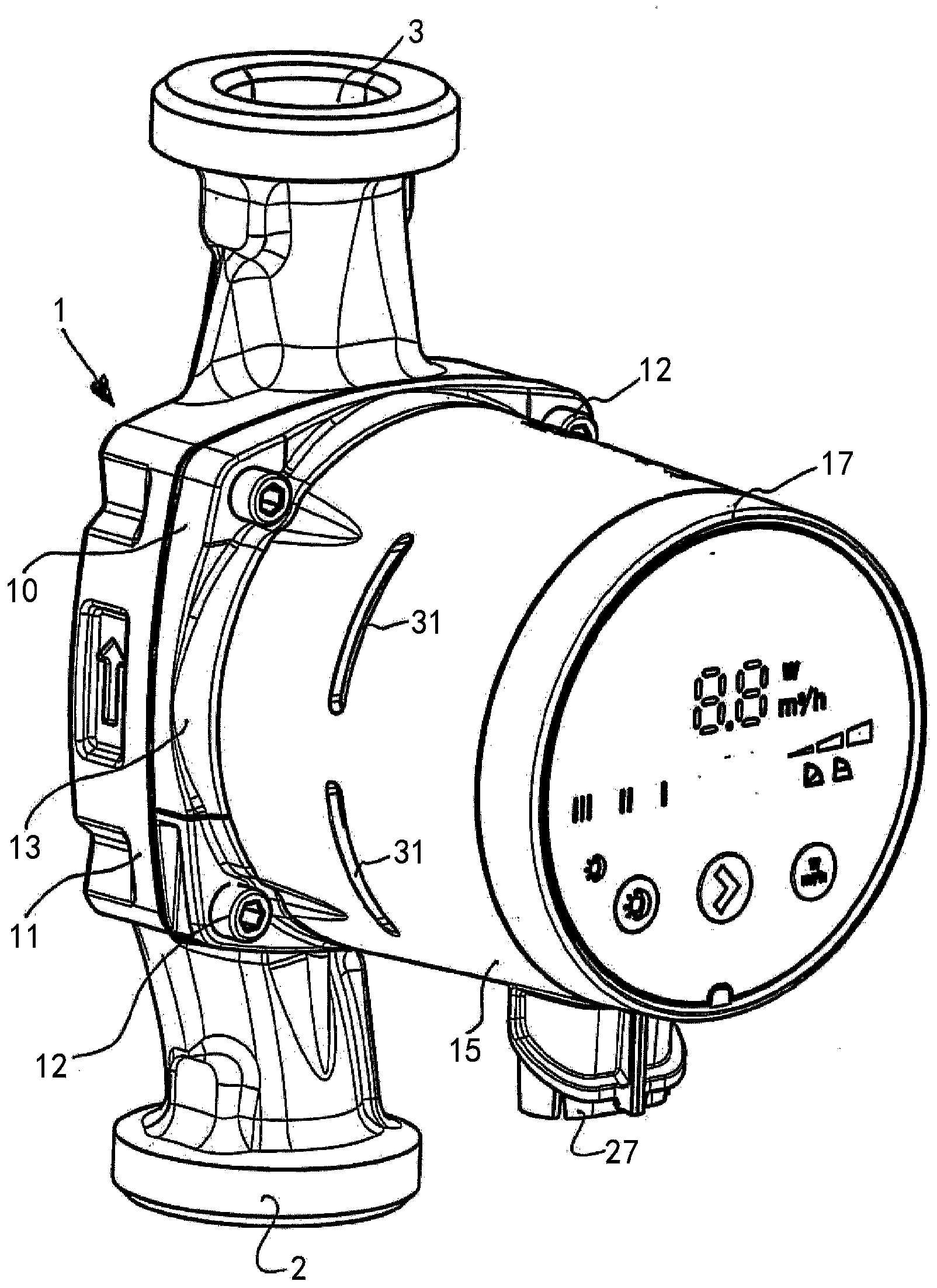
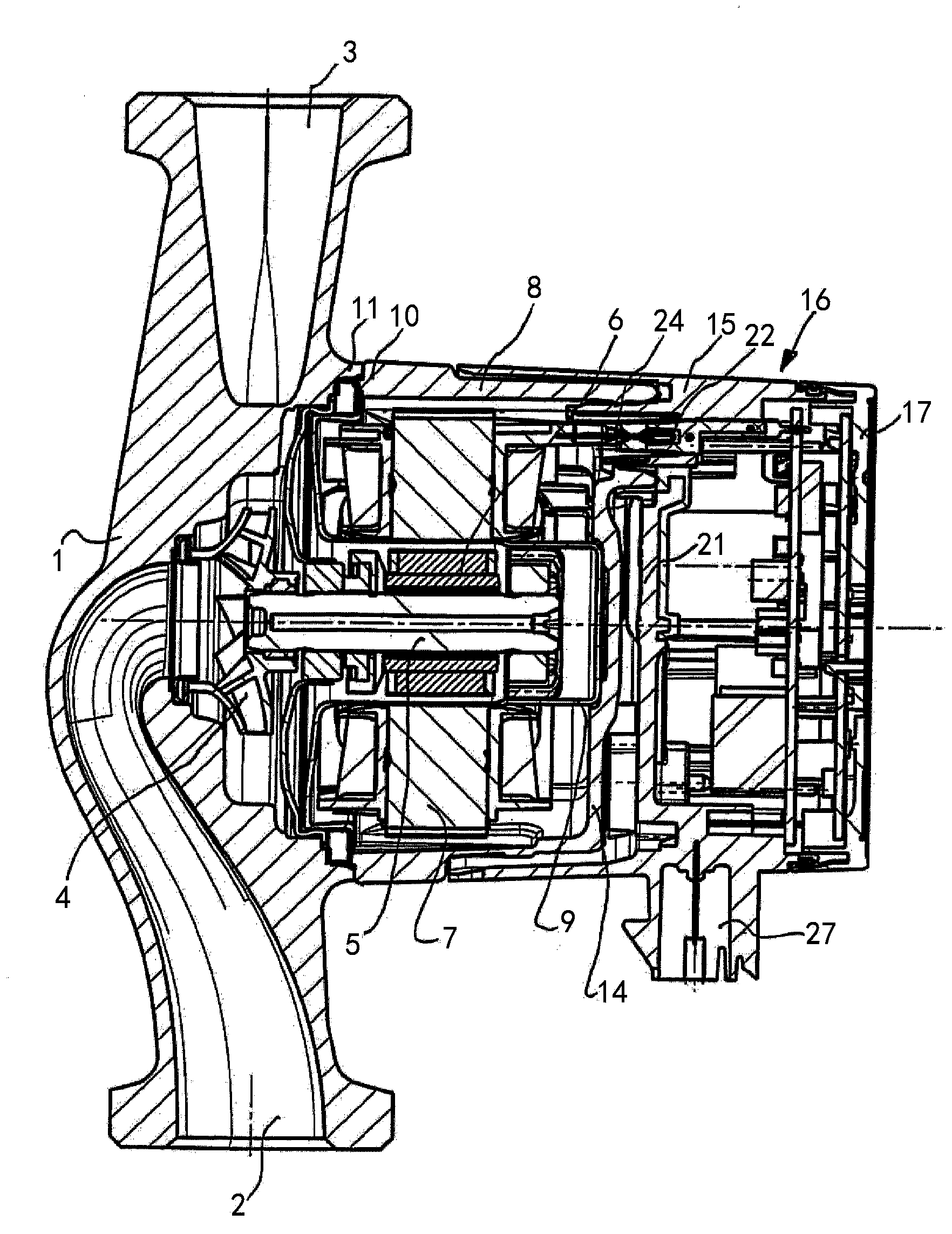
[0027] The heating circulation pump shown in the figure has a pump housing 1 comprising a suction sleeve 2 and a pressure sleeve 3 . A pump impeller 4 is rotatably arranged in the pump housing 1 in order to convey the conveying liquid at high pressure from the suction sleeve 2 into the pressure sleeve 3 in a known manner by rotating the pump impeller 4 . The pump impeller 4 is arranged on the shaft 5 , which simultaneously carries the rotor 6 of the electric motor, and the stator 7 of the electric motor is arranged in the stator housing 8 . The motor is a wet-running motor and has a liquid-filled slot 9 between the rotor 6 and the stator 7 .
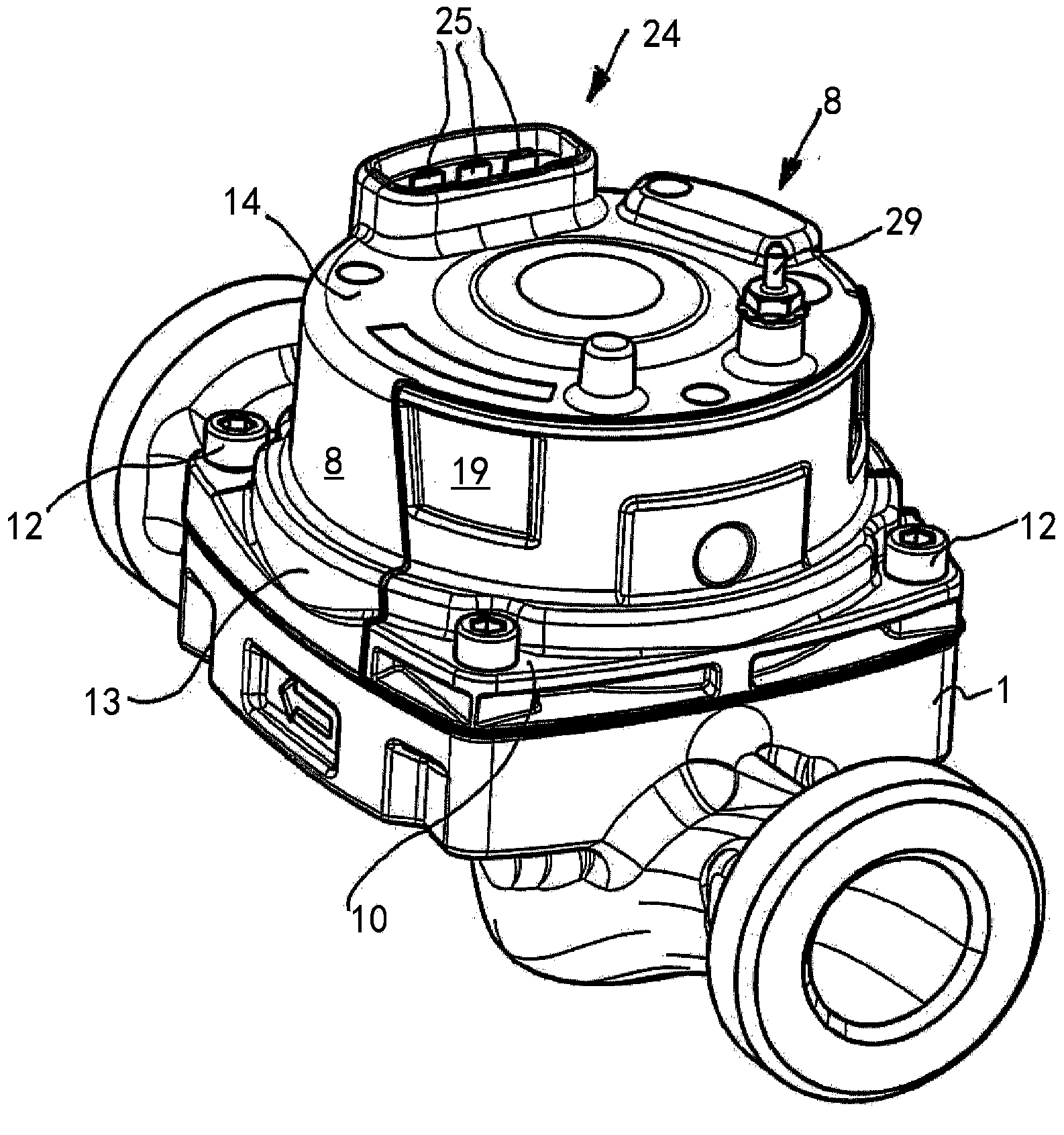
[0028] The pump housing 1 is designed to be open relative to the stator housing 8 . At its pump-side end, the stator housing 8 has a flange 10 which is connected to a flange 11 of the pump housing 1 and has a rounded square contour. Due to the circular design of the other part of the stator housing 8 , there will be a part in which the...
PUM
 Abstract
Description
Claims
Application Information
 - R&D Engineer
- R&D Manager
- IP Professional
- Industry Leading Data Capabilities
- Powerful AI technology
- Patent DNA Extraction
Browse by: Latest US Patents, China's latest patents, Technical Efficacy Thesaurus, Application Domain, Technology Topic, Popular Technical Reports.
© 2024 PatSnap. All rights reserved.Legal|Privacy policy|Modern Slavery Act Transparency Statement|Sitemap|About US| Contact US: help@patsnap.com