
Anti-ringing circuit for integrated voltage-reducing direct current/direct current (DC/DC) switch converter

A switching converter and step-down technology, applied in the direction of electrical components, output power conversion devices, etc., can solve problems affecting the normal operation of the system

Inactive Publication Date: 2013-12-04
UNIV OF ELECTRONICS SCI & TECH OF CHINA
View PDF6 Cites 15 Cited by
  • Summary
  • Abstract
  • Description
  • Claims
  • Application Information

AI Technical Summary

Problems solved by technology

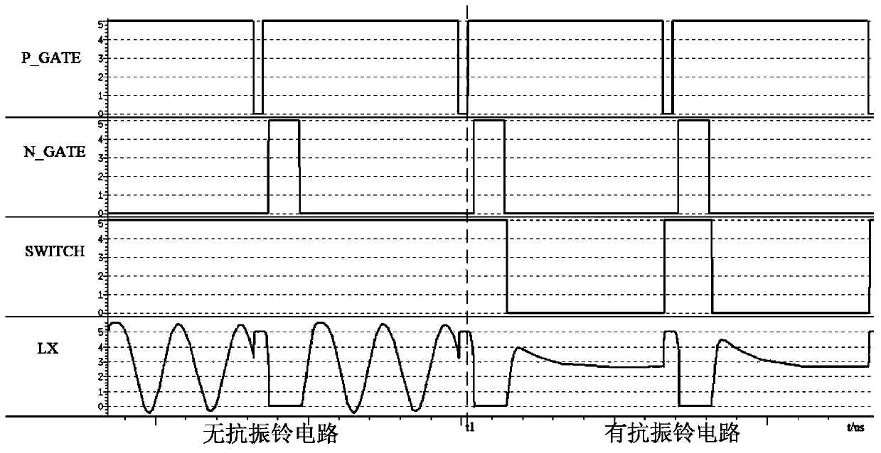
Due to the limiting effect of the parasitic diodes of MP and MN, the amplitude of the ringing is limited between -0.7V ~ VIN+0.7V, so sometimes high-order harmonics are generated. The fundamental and harmonics of these ringing, All may be coupled to sensitive circuits such as RF through the magnetic field leakage of the inductor or parasitic capacitance, affecting the normal operation of the entire system

Method used


Image

  • Anti-ringing circuit for integrated voltage-reducing direct current/direct current (DC/DC) switch converter
  • Anti-ringing circuit for integrated voltage-reducing direct current/direct current (DC/DC) switch converter
  • Anti-ringing circuit for integrated voltage-reducing direct current/direct current (DC/DC) switch converter

Examples


Embodiment Construction

[0017] Below in conjunction with accompanying drawing, describe technical scheme of the present invention in detail:

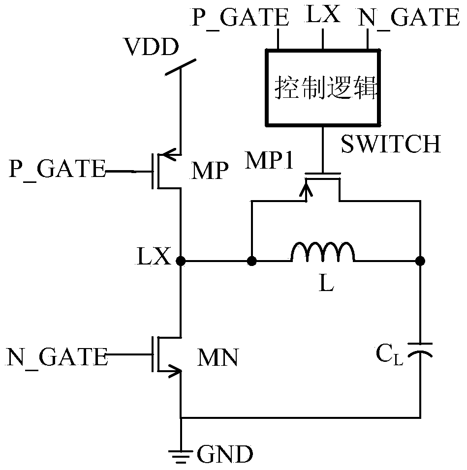
[0018] For the convenience of description, the first P-type field effect transistor MP is replaced by MP, the N-type field effect transistor MN is replaced by MN, the first gate logic signal P_GATE is replaced by P_GATE, and the second gate logic signal N_GATE is replaced by N_GATE, The second P-type field effect transistor MP1 is replaced by MP1, the ringing connection point formed by the drain of the first P-type field effect transistor MP, the drain of the N-type field effect transistor MN and one end of the inductor L is replaced by LX, and the second P The gate signal of the type field effect transistor MP1, that is, the output signal of the control logic circuit, is replaced by SWITCH.

[0019] Such as figure 1 As shown, the present invention consists of the main topology of the step-down DC / DC switching converter, a P-type field effect transistor MP1 c...


PUM


Abstract

The invention relates to an electronic circuit technology, in particular to an anti-ringing circuit in an integrated voltage-reducing direct current / direct current (DC / DC) switch converter. The anti-ringing circuit for the integrated voltage-reducing DC / DC switch converter is characterized by further comprising a P-type field effect transistor and a control logic circuit. A source electrode of the P-type field effect transistor is connected with one end of an inductor L, a drain electrode of the P-type field effect transistor is connected with the other end of the inductor L, a grid electrode of the P-type field effect transistor is connected with the input end of the control logic circuit, and three input ends of the control logic circuit are connected with a P-channel metal oxide semiconductor (PMOS) tube control signal, an N-channel metal oxide semiconductor (NMOS) tube control signal and a ringing signal respectively. The anti-ringing circuit for the integrated voltage-reducing DC / DC switch converter has the advantages that one P-type field effect transistor connected to two ends of the inductor is added based on a traditional voltage-reducing DC / DC switch converter, and the anti-ringing purpose of the integrated voltage-reducing DC / DC switch converter is achieved. The anti-ringing circuit is especially suitable for the DC / DC switch converter.

Description

technical field [0001] The invention relates to electronic circuit technology, in particular to an anti-ringing circuit in an integrated step-down DC / DC switching converter. Background technique [0002] The step-down DC / DC converter can work with high efficiency in a wide range of input and output voltages, making it an ideal power management topology in lithium-ion battery-powered electronic products. However, since the DC / DC converter works in the switching state, the large output noise voltage may affect sensitive units such as RF, especially when the DC / DC converter works in the inductor current discontinuous conduction mode (Discontinuous Current Mode, DCM), the LC loop formed by the inductance, the converter switching tube, and the parasitic capacitance of the freewheeling tube will produce serious high-frequency oscillation. Therefore, it is necessary to use a corresponding anti-ringing circuit for ringing attenuation. Although ringing can also be eliminated by per...

Claims


Application Information

Patent Timeline
Patent Type & Authority Applications(China)
IPC IPC(8): H02M1/44
Inventor 罗萍崔嘉杰王新宇陈剑洛廖鹏飞王磊万肖鹏包毅
Owner UNIV OF ELECTRONICS SCI & TECH OF CHINA
Learn More