
Band saw machine capable of adjusting the cutting angle of the band saw

A band saw machine and a technology for adjusting the band, which is applied to metal sawing equipment, sawing machine devices, metal processing equipment, etc., can solve the problems of worn-out band saw service life, acceleration, and insufficient applicability.

Active Publication Date: 2015-09-23
EVERISING MACHINE
View PDF6 Cites 0 Cited by
  • Summary
  • Abstract
  • Description
  • Claims
  • Application Information

AI Technical Summary

Problems solved by technology

[0003] The basic structure of the existing band saw machine includes: a machine base with a working table, a saw table that can move horizontally on the base and straddles the two sides of the working table, and a vertically movable The band saw mechanism is provided on the saw table and has a band saw, and the object to be sawed is placed on the work table, and the horizontal movement of the saw table and the vertical movement of the band saw mechanism are controlled to ensure that the object to be sawed Carry out sawing operation, however, it still has the defective that needs to improve immediately in actual use situation:
[0004] Since the band saw mechanism moves vertically to adjust the height position to change the sawing area of ​​the object to be sawed, and the band saw is still displaced synchronously during the vertical movement of the band saw mechanism, resulting in The band saw mechanism only has a fixed sawing angle (generally the angle of horizontal sawing), and cannot process with different sawing angles. Therefore, the applicability is obviously insufficient. In addition, when large-area horizontal During the sawing operation, due to the large contact area between the band saw and the object to be sawed, a larger power source must be consumed to drive the band saw to rotate, or even change the size of the band saw, so as to avoid accelerated consumption of the service life of the band saw

Method used


Image

  • Band saw machine capable of adjusting the cutting angle of the band saw
  • Band saw machine capable of adjusting the cutting angle of the band saw
  • Band saw machine capable of adjusting the cutting angle of the band saw

Examples


Embodiment Construction

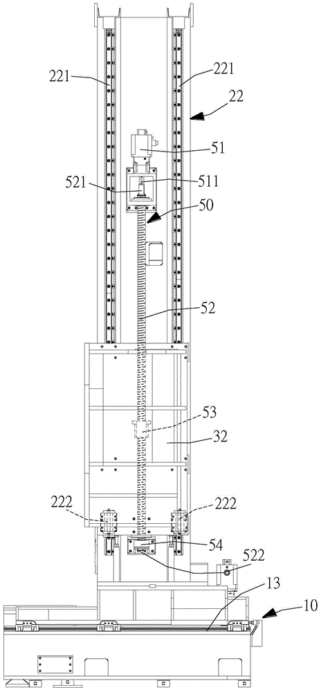
[0057] like Figures 1 to 4 and Figure 7 As shown, a band saw machine capable of adjusting the cutting angle of the band saw provided by the embodiment of the present invention mainly consists of a machine platform 10, a first saw base 21, a second saw base 22, a first saw Table 31, a second saw table 32, a first drive unit 40, a second drive unit 50, a band saw unit 60, and a band saw adjustment unit 70, wherein:

[0058] The machine 10 has a working platform 11 , a first side 12 disposed on one side of the working platform 11 , and a second side 13 disposed on the other side of the working platform 11 .

[0059] like Figure 2 to Figure 6 , the first saw seat 21 can be horizontally moved on the first side portion 12, and has two first slide rails 211 longitudinally arranged on the first saw seat 21, and a plurality of sliding rails 211 arranged on each of the first saw seats. For the first sliders 212 of the slide rails 211 , only one slider is shown on each of the first...


PUM


Abstract

The invention discloses a band-sawing machine capable of adjusting sawing angles of a band saw, and mainly solves the problem of insufficient applicability of the existing band-sawing machine having only one sawing angle. The band-sawing machine is mainly composed of a machine stand, a first saw seat, a second saw seat, a first saw bench, a second saw bench, a first drive unit, a second drive unit, a band saw unit and a band saw adjusting unit. The first and second drive units are controlled to drive the first and second saw benches to move up and down on the first and second saw seats so as to allow drive wheels and auxiliary wheels of the band saw unit not to be in the same horizontal plane and the band saw wound between the drive wheels and the auxiliary wheels to be inclined, the sawing angles of the band saw are changed, contact area of the band saw and a band-sawing item is reduced, power output can be saved, and applicability of the band-sawing machine can be improved.

Description

technical field [0001] The invention relates to a band saw machine, in particular to a band saw machine capable of adjusting the cutting angle of the band saw. Background technique [0002] The main purpose of the band saw machine is to perform sawing operations on metal, stone or wood waiting to be sawed, and through the sawing of the band saw machine, the metal, stone or wood waiting to be sawed can be formed into the desired size or shape , for subsequent processing or transportation. [0003] The basic structure of the existing band saw machine includes: a machine base with a working table, a saw table that can move horizontally on the base and straddles the two sides of the working table, and a vertically movable The band saw mechanism is provided on the saw table and has a band saw, and the object to be sawed is placed on the work table, and the horizontal movement of the saw table and the vertical movement of the band saw mechanism are controlled to ensure that the o...

Claims


Application Information

Patent Timeline
Patent Type & Authority Patents(China)
IPC IPC(8): B23D55/06
Inventor 赵淑佳
Owner EVERISING MACHINE
Learn More