Rolling bearing device for wheel

A technology for rolling bearings and wheels, which is applied in the directions of wheel bearings, rolling contact bearings, and rotating bearings, etc. It can solve the problems of insufficient strength of the flange and achieve the effect of weight reduction

Inactive Publication Date: 2013-11-27
JTEKT CORP
View PDF7 Cites 0 Cited by
  • Summary
  • Abstract
  • Description
  • Claims
  • Application Information

AI Technical Summary

Problems solved by technology

Therefore, in consideration of the stress concentration on the flange portion of the shaft member, there is a fear that the strength of the flange portion becomes insufficient if the thickness of the flange portion is uniformly reduced.

Method used


Image

  • Rolling bearing device for wheel
  • Rolling bearing device for wheel
  • Rolling bearing device for wheel

Examples


Embodiment Construction

[0030] Modes for carrying out the invention will be described based on the embodiments.

[0031] will be based on Figure 1 to Figure 9 Embodiments of the present invention will be described.

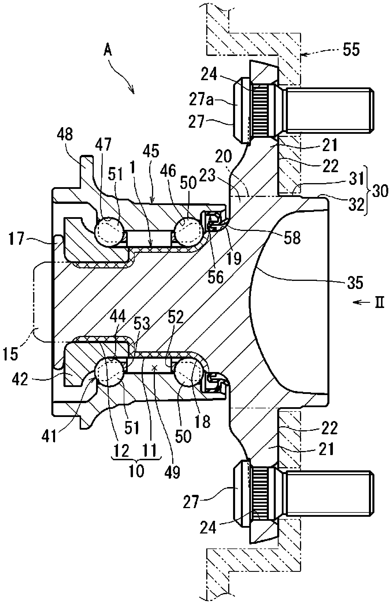
[0032] Such as figure 1 As shown, the hub unit as the rolling bearing device for the wheel A is formed as a unit including the double row angular contact ball bearing 41 and the shaft member 1 of the rolling bearing device A integrally.

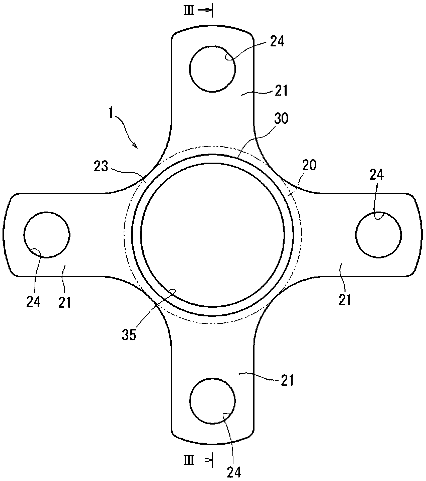
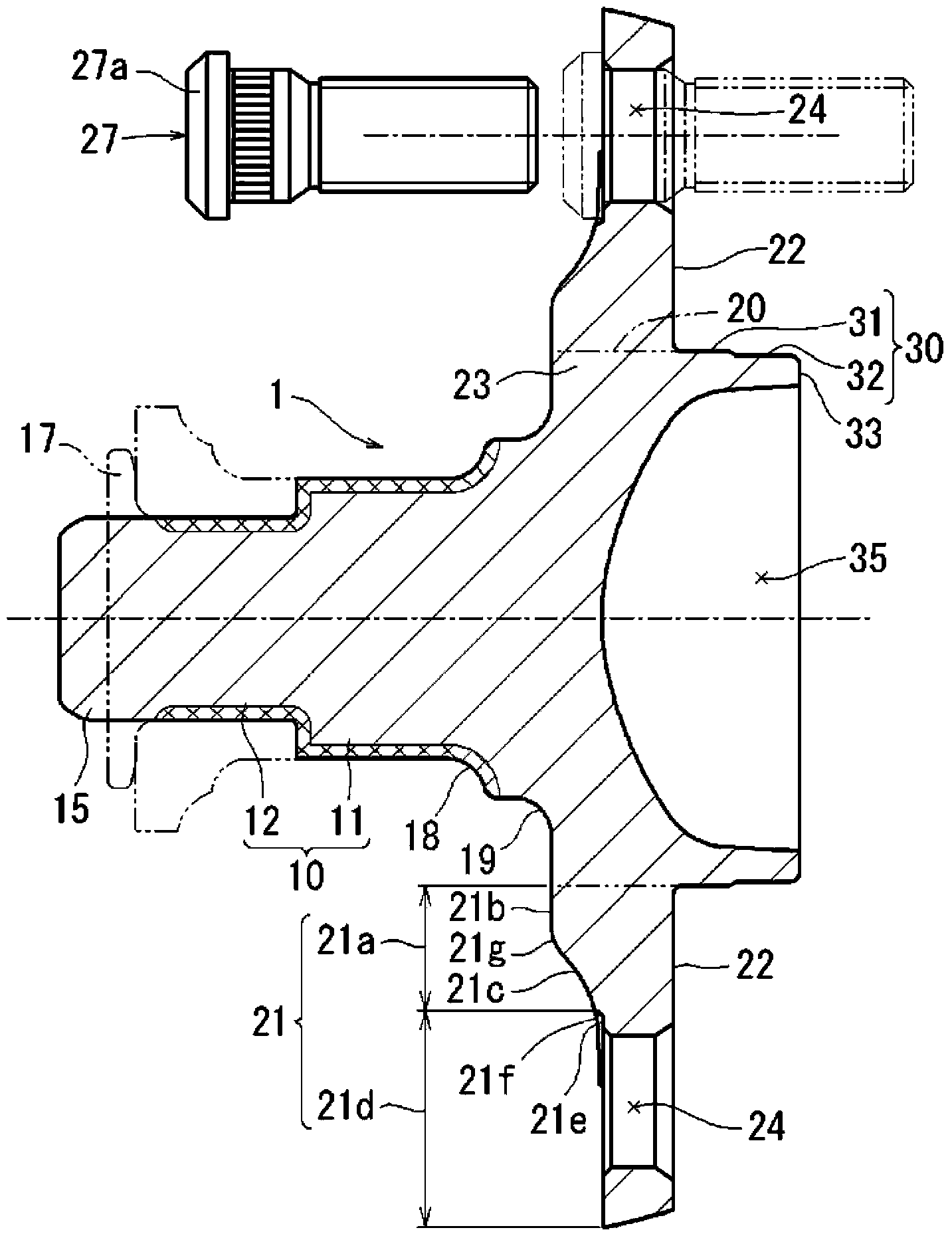
[0033] The shaft member 1 of the rolling bearing device A integrally includes: a shaft portion 10; a fitting shaft portion 30 formed at one end portion of the shaft portion 10, the fitting shaft portion 30 having a a larger diameter and a central hole for fitting a wheel (not shown) on the fitting shaft portion 30; a flange base 23 positioned between the shaft portion 10 and the fitting shaft portion 30; and a plurality of flange portions 21 provided on the outer circumferential surface of the flange base portion 23 to extend radially outward in the...


PUM


Abstract

A flange section, provided to a shaft member in a rolling bearing device for a wheel, is provided with an outer flange section and an inner flange section which is thicker than the outer flange section in the cross-sectional view. In the inner flange section, the shape of the flange surface on the side on which the bearing-surface section of a hub bolt is arranged is made to be an inclined concave surface which gradually becomes thinner from the base-end section in the radial direction, toward the outer-side in the radial direction. The inclined concave surface is formed as a surface for which the thickness of the inner flange section becomes smaller in a uniform manner, in relation to the width direction of the flange section, toward the outer-side in the radial direction.

Description

technical field [0001] The invention relates to a rolling bearing device for a wheel. Background technique [0002] In general, there is a known rolling bearing device which includes a shaft member having: a shaft portion on an outer peripheral surface of which an inner ring raceway surface is formed; a fitting shaft portion forming at one end portion of the shaft portion; and a plurality of flange portions positioned between the shaft portion and the fitting shaft portion, the plurality of flange portions radially along the radial direction extending outward and in the plurality of flange portions are provided with bolt holes penetrating the flange portions in which hub bolts are disposed, and such rolling bearing devices are disclosed in, for example, Patent Document 1 and Patent Document 2 middle. [0003] The shaft members of the rolling bearing devices disclosed in Patent Document 1 and Patent Document 2 are each formed by sideways extrusion processing in cold forging...

Claims


Application Information

Patent Timeline
Patent Type & Authority Applications(China)
IPC IPC(8): B60B27/00B21K1/05B60B35/02F16C33/58
CPCB60B2380/75F16C19/186B60B2380/82B21K1/05F16C2326/02B60B27/0005B60B35/025B21K1/40Y02T10/86
Inventor 中尾一纪
Owner JTEKT CORP
Why Eureka
Try Eureka