A wire feeding jig

A feeding and jig technology, applied in circuit/collector parts, electrical components, circuits, etc., can solve problems such as affecting processing, and achieve the effect of improving security and structural safety and reliability

Inactive Publication Date: 2015-12-23
深圳汇准科技有限公司
View PDF4 Cites 0 Cited by
  • Summary
  • Abstract
  • Description
  • Claims
  • Application Information

AI Technical Summary

Problems solved by technology

[0003] In order to solve the problem that the feeding action of the wire feeding jig in the prior art is suddenly stopped, because the feeding plate has the inertia to continue to rotate, the feeding side will still continue to rotate forward several times, causing the wire to continue to be conveyed, so that the wires that are conveyed may be It will be wound on the crimping mechanism and affect the subsequent processing. The invention provides a wire feeding jig with simple structure, easy to use, and can quickly stop the rotation of the feeding tray.

Method used


Image

  • A wire feeding jig

Examples


Embodiment Construction

[0011] The present invention will be further described below in conjunction with the accompanying drawings.

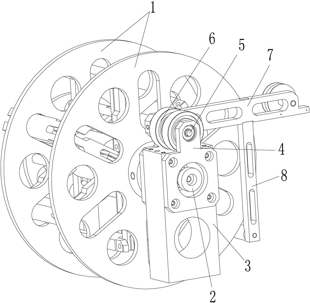
[0012] Such as figure 1 As shown, a wire feeding fixture includes two circular feeding discs 1, a rotating shaft 2, a support seat 3, a bearing seat 4, a drive shaft 5, a torsion spring 6, a cantilever 7 and a brake arm 8, and one of the circles A support seat 3 is arranged on the outer side of the shaped feed tray 1, and the rotating shaft 2 passes through two circular feed trays 1 and the support seat 3 in turn, and bearing seats 4 are respectively arranged at both ends above the support seat 3, and the drive shaft 5 Through the two bearing seats 4 , two torsion springs 6 for controlling the rotation of the drive shaft 5 are arranged on the part of the drive shaft 5 between the two bearing seats 4 . One end of the drive shaft 5 is connected with a cantilever 7 , and the bottom of the cantilever 7 is connected with a brake arm 8 capable of resisting the circular feed...


PUM


Abstract

The invention discloses a wire feeding jig. The wire feeding jig comprises two round feeding plates, a rotating shaft and a supporting seat, and the supporting seat is arranged on the outer side of one round feeding plate. The wire feeding jig is characterized by further comprising a torsion spring, a driving shaft, a suspension arm and a braking arm. The rotating shaft sequentially penetrates through the two round feeding plates and the supporting seat; the driving shaft is arranged above the supporting seat; the torsion spring used for controlling the driving shaft to rotate is arranged on the driving shaft; the suspension arm is connected to one end of the driving shaft; the braking arm used for propping the round feeding plates is connected to the bottom of the suspension arm. The wire feeding jig solves the problems that when feeding motion of the wire feeding jig is suddenly stopped, the feeding plates will still continue rotating forwards for several circles because of continuing rotating under the action of inertia, the wires will be continuously conveyed, and accordingly additionally-conveyed wires will be wound on a pressing connection mechanism and follow-up processing is affected. The wire feeding jig is simple in structure, convenient to use and capable of ensuring that the feeding plates fast stop rotating.

Description

technical field [0001] The invention relates to a feeding jig, in particular to a wire feeding jig. Background technique [0002] At present, in the process of crimping the terminal, the wire needs to be conveyed to the crimping position through the feeding tray. When the wire is delivered to the position, the crimping operation will be performed. At this time, the feeding tray will stop rotating and no feeding operation will be performed. However, the feeding action of the feeding tray is stopped suddenly. Since the feeding side has the inertia of continuous rotation, the feeding side will still continue to rotate forward for a few turns, causing the wire to continue to be conveyed, so that the wires conveyed more may be wound on the crimping mechanism. , affecting subsequent processing. Contents of the invention [0003] In order to solve the problem that the feeding action of the wire feeding jig in the prior art is suddenly stopped, because the feeding plate has the i...

Claims


Application Information

Patent Timeline
Patent Type & Authority Patents(China)
IPC IPC(8): H01R43/052
Inventor 黄锦章
Owner 深圳汇准科技有限公司
Why Eureka
Try Eureka