
Protective cap for column base of transformer substation power distribution unit steel frame

A technology for power distribution devices and steel frame columns, which is applied in the field of substation infrastructure protection devices, can solve problems such as corrosion and on-site construction difficulties, achieve the effects of reducing workload, simplifying on-site installation procedures, and improving sealing performance

Active Publication Date: 2013-11-27
STATE GRID CORP OF CHINA +1
View PDF6 Cites 0 Cited by
  • Summary
  • Abstract
  • Description
  • Claims
  • Application Information

AI Technical Summary

Problems solved by technology

The connection form of the steel structure (support) frame and the foundation is divided into two types: the cup mouth insertion type and the bolt connection type. Due to the technical requirements of the substation construction, the top surface elevation of the structure (support) frame foundation is generally 200mm lower than the ground, and the column foot part If the steel structure is not protected, it is easy to be corroded by the surface water in the soil. The conventional protective cap is cast in the form of plain concrete, and the construction on site is relatively difficult.

Method used


Image

  • Protective cap for column base of transformer substation power distribution unit steel frame
  • Protective cap for column base of transformer substation power distribution unit steel frame
  • Protective cap for column base of transformer substation power distribution unit steel frame

Examples


Embodiment Construction

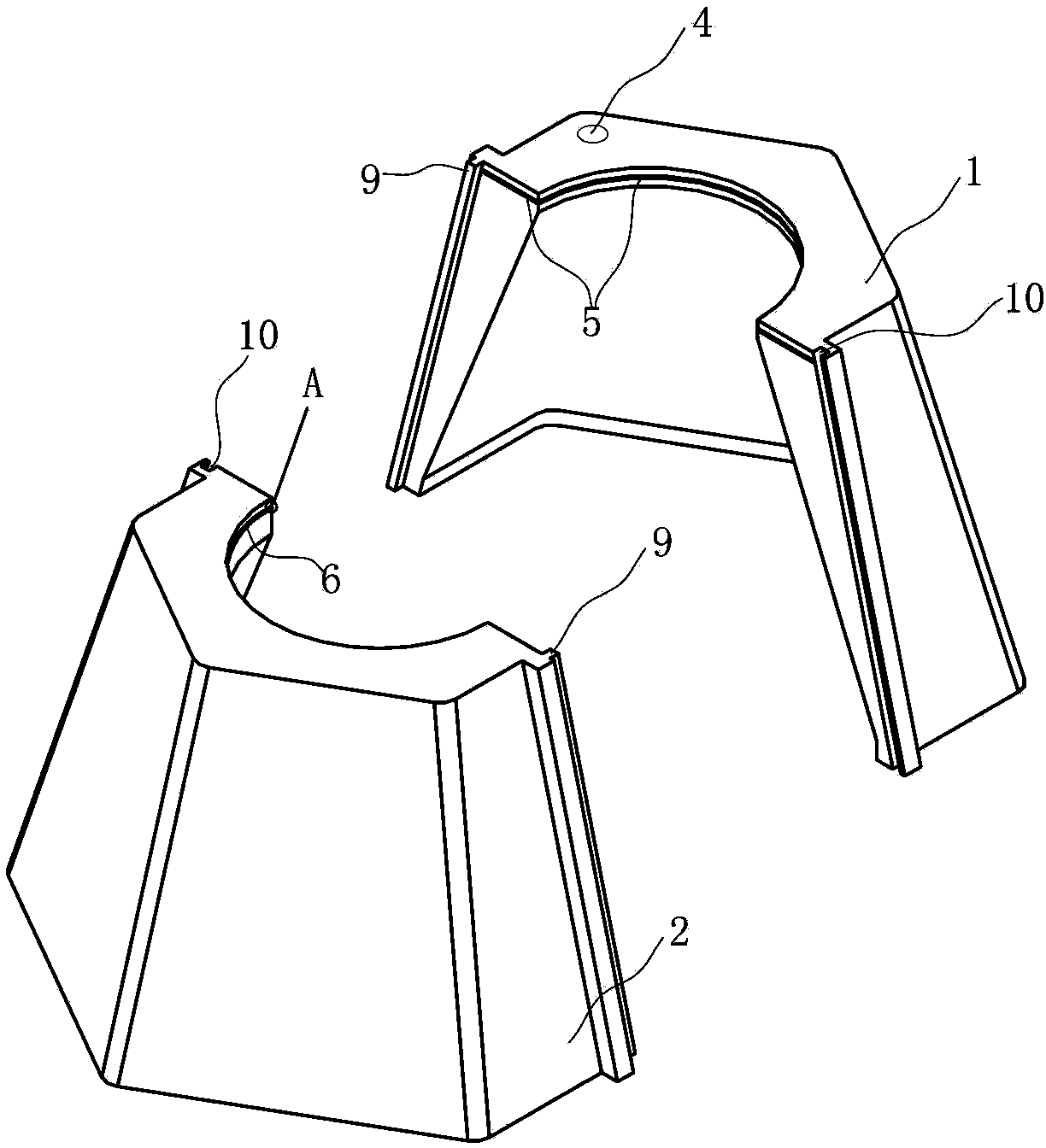
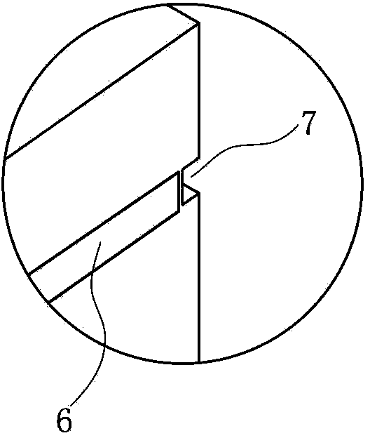
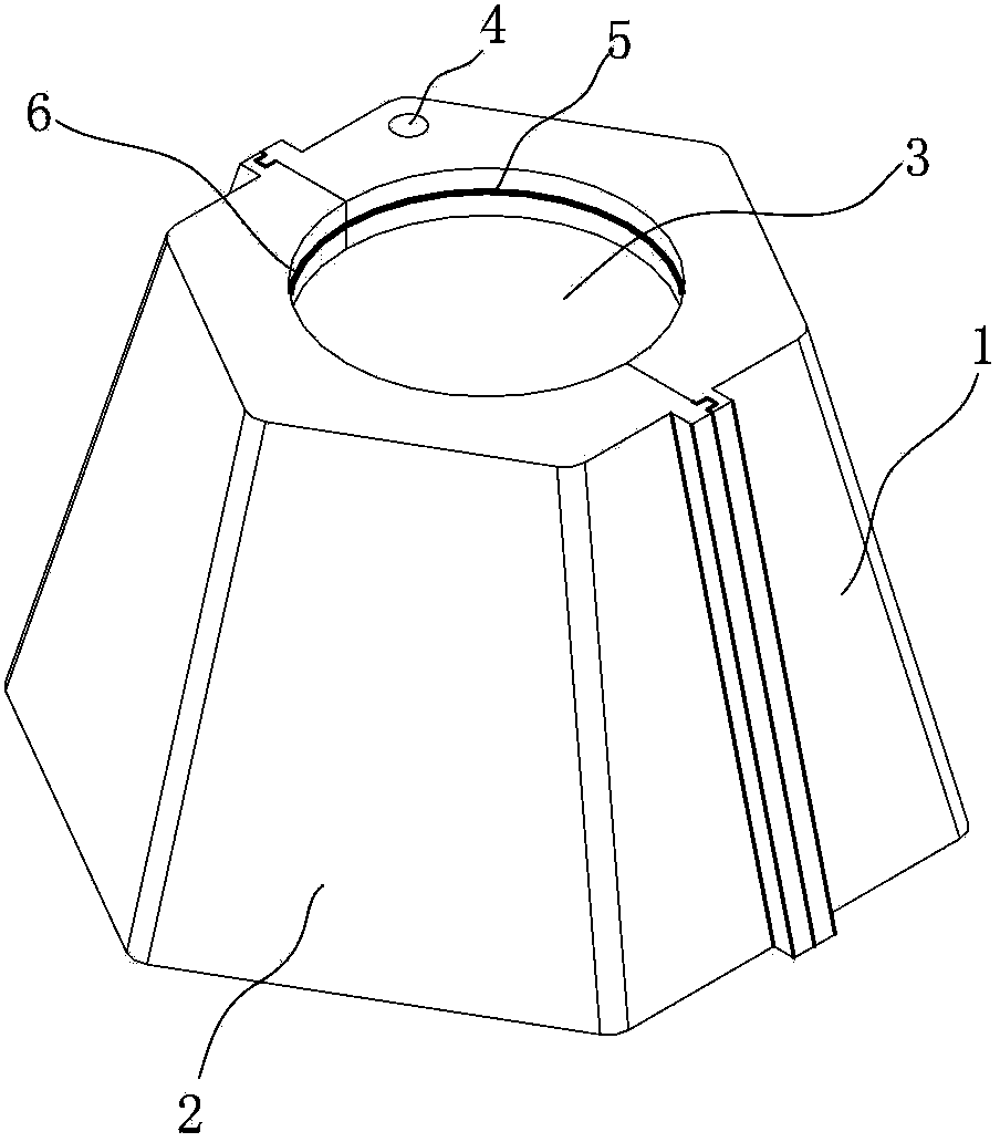
[0025] As shown in the figure, the protective cap of the steel frame column foot of the power distribution device of the substation, the plastic cap body is formed by two half cap bodies 1 and 2 left and right sealed butt joints, and the center of the upper end surface of the cap body forms a positioning hole 3 for sealing connection , the upper end face of each half cap body forms half described positioning hole, and the upper end face of one half cap body 1 wherein has a butter filling port 4 for injecting butter into the inner chamber of the cap body, the butter filling port 4 places are connected with bolts 13 for sealing. The bottom of the cap body is open, and the lower end surface is a plane. The cap is in the shape of a platform with a small top and a large bottom.

[0026] A continuous transversely arranged rubber waterstop 5 is embedded on the two butt joint surfaces of the half cap body 1 top and the hole wall of the half positioning hole. A continuous horizontall...


PUM


Abstract

The invention discloses a protective cap for a column base of a transformer substation power distribution unit steel frame. In the prior art, if a steel structure of the column base portion of the transformer substation power distribution unit steel frame is not protected, the steel structure will be corroded by surface water in soil easily, a traditional protective cap is formed by plain concrete through cast-in-place, and site construction is difficult. According to the technical scheme, the protective cap for the column base of the transformer substation power distribution unit steel frame comprises a plastic cap body, and is characterized in that the cap body is formed in a manner that two half cap bodies are in butt connection left and right in a sealing mode, a locating hole for sealing connection is formed in the center of the upper end face of the cap body, one half locating hole is formed in the upper end face of each half cap body, a grease injection port is formed in the upper end face of one of the half cap bodies, grease can be injected into an inner cavity of the cap body through the grease injection port, and a sealing piece is connected to the grease injection port. All parts of the protective cap for the column base can be machined on site through a mould and installed on site, and therefore the protective cap for the column base is convenient to dismount and mount; besides, the protective cap for the column base has good integrality and water tightness.

Description

technical field [0001] The invention relates to a protective device for substation infrastructure, in particular to a protection cap for the steel frame column feet of a power distribution device in a substation. Background technique [0002] The structure (support) of substation power distribution device can be divided into steel structure and concrete structure according to the material. With the improvement of the country's overall economic strength and the voltage level of substations, in the selection of structural materials for substation power distribution device structures (supports), while considering safety, it is also necessary to consider structural economy, processing and manufacturing and construction. , The aesthetics of finished product quality, etc. [0003] With the rapid development of my country's economy, my country's steel output has also increased significantly. In 2005 alone, my country's annual steel output was about 342 million tons, accounting for...

Claims


Application Information

Patent Timeline
Patent Type & Authority Applications(China)
IPC IPC(8): E02D31/06
Inventor 方瑜张弘陈飞黄忠华吴祖咸胡宇鹏吴冰邵斐童军许琳高美金高亚栋俞辰颖滕永禧候建生尹康
Owner STATE GRID CORP OF CHINA
Learn More