
gas compressor

一种压缩机、气体的技术,应用在液体变容式机械、机械设备、机器/发动机等方向,能够解决压缩机效率劣化等问题,达到减轻有害影响、延长使用寿命、减轻磨损的效果

Active Publication Date: 2016-01-20
QUINTUS TECH
View PDF7 Cites 0 Cited by
  • Summary
  • Abstract
  • Description
  • Claims
  • Application Information

AI Technical Summary

Problems solved by technology

However, the arrangement of the inlet and outlet as disclosed can lead to a deterioration in the efficiency of the compressor

Method used


Image

  • gas compressor
  • gas compressor
  • gas compressor

Examples


Embodiment Construction

[0040] In the following description, the invention is described with reference to a piston compressor.

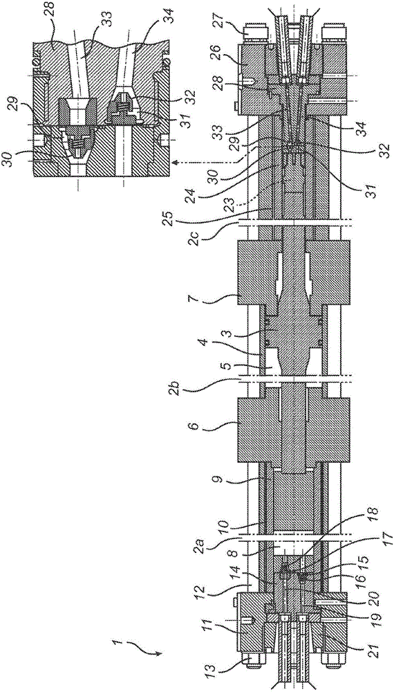
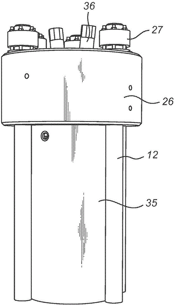
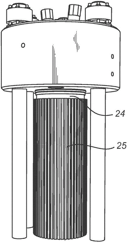
[0041] exist figure 1 , a cross-sectional view of a piston compressor 1 is shown. Since the piston compressor 1 is elongated in the horizontal direction, the drawing is provided with partitions 2a, 2b and 2c to make the drawing more compact. Therefore, taking this into consideration, the dimensional relationship in the horizontal direction in the drawings of the piston compressor 1 is explained.

[0042] In the piston compressor 1, the piston 3 is set in the central container 4, the oil is periodically pumped into the central container space 5, to both sides of the piston 3, so that the pressure from the oil forces the piston 3 in the central container Reciprocate back and forth in space 5.

[0043] A first inner gable 6 and a second inner gable 7 are arranged along the axial direction of the central container 4 , and the first inner gable 6 and the second inner gable 7 ...


PUM


Abstract

The invention discloses a high-pressure piston compressor (1) for compressing gas, comprising: a container (4) having a container chamber (8, 23), wherein the piston (3) is guided reciprocally for During operation of the piston compressor, gas is compressed in the container chamber; inlet valve housing (17, 29) including inlet valve (18, 30); and outlet valve housing (16, 32) including outlet valve 15, 31), wherein the inlet valve housing and the outlet valve housing are mounted within a portion of the vessel chamber wall (14, 28), and wherein the portion of the vessel chamber wall surrounds the inlet valve housing and the outlet valve housing such that the portion of the vessel chamber wall is at the inlet valve housing and the outlet during operation of the reciprocating compressor in response to the pressure on the inlet valve housing and the outlet valve housing from the gas in the vessel chamber An isobaric backpressure is created on the valve housing.

Description

technical field [0001] The invention relates to piston compressors for compressing gases. Background technique [0002] Compressed gas is used as a medium in different technical fields, where examples of equipment, processes and operations using compressed gas can be refrigerators, densification of powdered or cast materials in high-pressure presses and oil service operations. Among various well-known techniques for compressing gas, a piston compressor constitutes a specific example of compression equipment. Piston compressors for small to intermediate pressures are common in automotive applications, while larger piston compressors are common in larger industrial and petroleum applications. Hydraulically driven piston compressors are usually arranged such that a central piston is arranged in a hydraulic cylinder. The piston divides the cylinder into two subspaces of the cylinder into which oil is pumped periodically such that pressure from the oil forces the central piston...

Claims


Application Information

Patent Timeline
Patent Type & Authority Patents(China)
IPC IPC(8): F04B9/109F04B9/115F04B25/00F04B39/12F04B39/10
CPCF04B9/1095F04B9/115F04B25/005F04B39/10F04B39/121F04B39/125F04B1/00
Inventor 罗杰·图恩霍姆
Owner QUINTUS TECH
Learn More