Automatic terminal crimping machine

A terminal crimping machine and terminal crimping technology, applied in the direction of electrical components, circuits, connections, etc., can solve the problems of low efficiency, low efficiency, and impossibility of manual stripping

Inactive Publication Date: 2013-11-20
DONGGUAN XINZHE AUTOMATION EQUIP
View PDF4 Cites 9 Cited by
  • Summary
  • Abstract
  • Description
  • Claims
  • Application Information

AI Technical Summary

Problems solved by technology

Among them, the most primitive method is manual processing, that is, after the wires are stripped and put on the metal terminals, the terminals are riveted to the wires with terminal pliers. This type of processing method is inefficient and high in labor costs, and gradually cannot meet the requirements of mass production. , It is still used when there are only a small number of orders; later, some manufacturers stamped the terminal and the end of the wire harness through a punching machine after manual stripping. The efficiency of wires is still very low, and the consistency is not good, so it is gradually replaced by automatic crimping machines; in order to further improve the efficiency of terminal crimping, some manufacturers have developed automatic terminal crimping machines that can automatically strip wires and automatically crimp terminals. , which greatly improves the production efficiency, and the highest speed reaches 9000 crimping terminals per hour at both ends. However, the existing automatic terminal crimping machines generally have the following problems: 1. Generally, they are aimed at single-wire processing, and multiple wire harnesses Most of the crimping machines cannot realize the terminal crimping of multiple wires. Generally, a single wire is processed first and then bundled; 2. The terminals at both ends of the wire are the same terminal. When it is necessary to crimp different terminals at both ends of the wire harness time, the existing crimping machine cannot achieve

Method used


Image

  • Automatic terminal crimping machine
  • Automatic terminal crimping machine
  • Automatic terminal crimping machine

Examples


Embodiment Construction

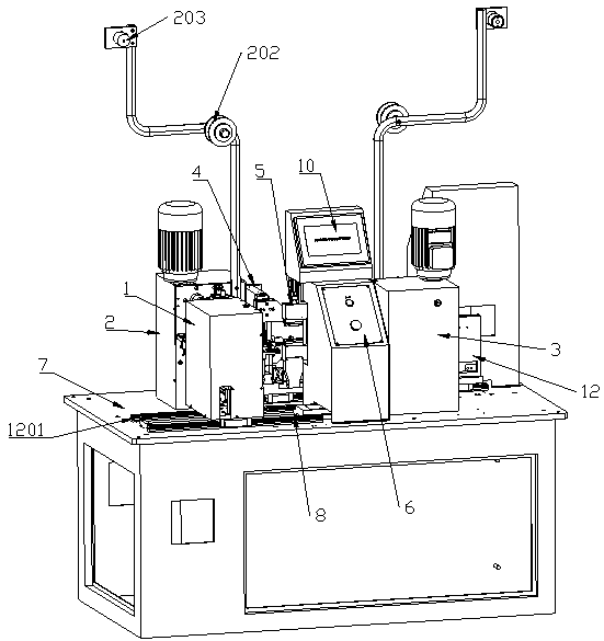
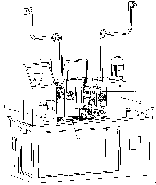
[0039] like figure 1 and figure 2 As shown, the fully automatic terminal crimping machine of this embodiment includes a wire feeding mechanism 1 for transmitting the wire harness of the terminal to be crimped;

[0040] The first crimping mechanism 2 divides the first end of the wire harness and performs terminal crimping on the divided wires in sequence;

[0041] The second crimping mechanism 3 divides the second end of the wire harness and performs terminal crimping on the divided wires in sequence;

[0042] The front peeling and shifting mechanism 4 performs peeling operation on the first end of the wire harness, and moves the wire harness to the second pressing mechanism after the first end is crimped;

[0043] The rear peeling and tangent mechanism 5 performs tangent operation on both ends of the wire harness, and performs peeling operation on the second section during the process of moving the wire harness to the second pressing mechanism after the first end is crimped...


PUM


Abstract

The invention relates to wiring harness terminal crimping equipment, particularly to an automatic terminal crimping machine which comprises a harness feeding mechanism, a first crimping mechanism, a second crimping mechanism, a front peeling and moving mechanism, a back peeling and harness cutting mechanism, and an electrical control box used for setting operation parameters and running operation, wherein the mechanisms are mounted on a platform surface; the harness feeding mechanism is arranged on a first translating mechanism for driving the harness feeding mechanism to slide between the back peeling and harness cutting mechanism and the first crimping mechanism; the front peeling and moving mechanism is arranged on a second translating mechanism for moving wiring harnesses of which the first ends are crimped to the second crimping mechanism. The automatic terminal crimping machine is used for performing terminal crimping to the two ends of wiring harnesses through the first crimping mechanism and the second crimping mechanism, and enabling the wiring harnesses to move between steps through the moving mechanisms, so as to realize the automation of the two ends crimping of the wiring harnesses; besides, the terminal crimping operation on wiring harnesses formed by multi-strand wires can be realized as the crimping mechanisms separate the wiring harnesses before crimping the wiring harnesses.

Description

technical field [0001] The invention relates to a wire harness terminal crimping device, in particular to an automatic terminal crimping machine. Background technique [0002] Wire harnesses are wires used to connect input and output terminals for electrical transmission or signal transmission. They are widely used in various charged devices and equipment, such as TVs, mobile phones, cameras, cars, air conditioners, radios, airplanes, trains, etc. Open the wiring harness. In order to realize electrical connection more conveniently, the wire harness is generally fixedly connected with terminals at both ends. With the development of technology, the way of connecting terminals at both ends of the wire harness has also gradually developed. Among them, the most primitive method is manual processing, that is, after the wire is stripped and put on the metal terminal, the terminal is riveted to the wire with the terminal pliers. This kind of processing method has low efficiency an...

Claims


Application Information

Patent Timeline
Patent Type & Authority Applications(China)
IPC IPC(8): H01R43/05H01R43/052
Inventor 范小军
Owner DONGGUAN XINZHE AUTOMATION EQUIP
Why Eureka
Try Eureka