Spectral electrolytic cell suitable for in-situ characterization of Raman spectrum

A Raman spectroscopy and electrolytic cell technology, which is applied in the field of spectral electrolytic cells to achieve the effects of easy operation, uniform power lines, and simple assembly

Inactive Publication Date: 2013-11-20
XIAMEN UNIV
View PDF5 Cites 24 Cited by
  • Summary
  • Abstract
  • Description
  • Claims
  • Application Information

AI Technical Summary

Problems solved by technology

[0004] The purpose of the present invention is to solve the problem that the existing Raman technology is difficult to combine with electrochemical technology, to provide good sealing, no liquid leakage, convenient control of the thickness of the liquid layer between the spectral window and the working electrode, and its assembly and A spectroscopic electrolytic cell suitable for Raman spectroscopic in-situ characterization with easy cleaning

Method used


Image

  • Spectral electrolytic cell suitable for in-situ characterization of Raman spectrum
  • Spectral electrolytic cell suitable for in-situ characterization of Raman spectrum
  • Spectral electrolytic cell suitable for in-situ characterization of Raman spectrum

Examples


Embodiment 1

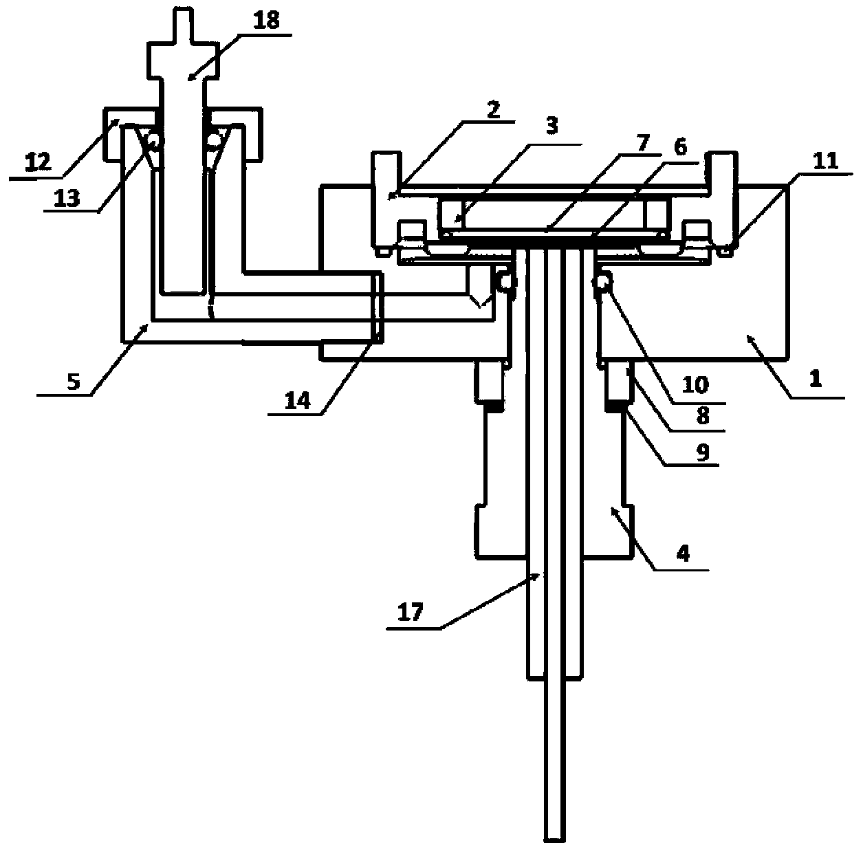
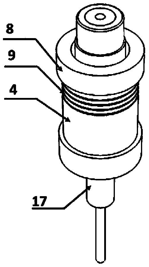
[0031] Such as Figure 1-7 As shown, the embodiment of the present invention is provided with a spectral electrolytic cell body 1, a spectral electrolytic cell top cover 2, a window sealing ring 3, an electrode sleeve 4, a reference electrode connection end 5, a spectral window 6, an O-ring 7, Limit ring 8, limit adjustment gasket 9, O-ring 10, sealing gasket 11, reference electrode sealing cover 12, O-ring 13, sealing gasket 14, counter electrode lead 15, counter electrode 16, working electrode 17. Reference electrode 18.

[0032] The spectral electrolytic cell body 1 is connected to the spectral electrolytic cell top cover 2, and the window sealing ring 3 is fixed on the spectral electrolytic cell top cover 2; the middle position of the spectral electrolytic cell body 1 is provided with a first hole 1-1 , the electrode cover 4 is located in the first hole 1-1, the first hole 1-1 is provided with a groove for placing the O-ring 10, and the sealing is realized by the contact ...

Embodiment 2

[0050] This embodiment is a further illustration of placing an O-ring at the through-hole groove in the middle of the cell body in Example 1 to realize the sealing between the cell body and the working electrode. The O-ring is not limited to a circular sealing ring and can be various Gaskets of various shapes and materials.

Embodiment 3

[0052] This embodiment is a further description of placing an O-ring at the through-hole groove in the middle of the cell body in Example 1 to realize the sealing between the cell body and the working electrode. The sealing ring seal is only a mode of this design, and it can also be threaded or sealed by a tight fit. A combination of these sealing methods is also possible.


PUM


Abstract

The invention discloses a spectral electrolytic cell suitable for in-situ characterization of a Raman spectrum and relates to a spectral electrolytic cell. The spectral electrolytic cell is provided with a spectral electrolytic cell body, a top cover, an electrode sleeve, a reference electrode connection end, a spectral window sheet, limiting rings, limiting adjustment gaskets, reference electrode sealing covers, a counter electrode and a working electrode, wherein the cell body is connected with the top cover; window sheet sealing rings are fixed on the top cover; a first hole is formed in the middle of the cell body; the electrode sleeve is arranged in the first hole; a second hole is formed in the bottom in the cell body and is connected with the reference electrode connection end; a through hole is formed in the electrode sleeve; the upper end of the reference electrode connection end is connected with the reference electrode sealing covers; the spectral window sheet is arranged at the bottom in the top cover; small holes are formed in the middles of the reference electrode sealing covers; a third hole is formed in the side edge of the cell body; the counter electrode is arranged in the third hole; the limiting rings and the limiting adjustment gaskets are arranged at the periphery of the electrode sleeve; one end of the counter electrode is a sphere; a trench is formed in the bottom of the top cover; a gas storage tank is arranged beside the trench; a gas exhaust hole is formed in the upper end of the gas storage tank.

Description

technical field [0001] The invention relates to a spectroscopic electrolytic cell, in particular to a spectroscopic electrolytic cell suitable for Raman spectrum in-situ characterization. Background technique [0002] The traditional electrochemical method mainly measures the electrode potential or current, and obtains the macroscopic average information of the electrode interface. It is difficult to provide the behavior of molecules at the surface interface from the molecular structure level. Applying molecular spectroscopic techniques such as ultraviolet, infrared, and Raman to the field research of electrochemistry can directly obtain information about the interaction mode, adsorption orientation, and coverage of species on the electrode surface at the molecular level. [0003] Raman spectroscopy, especially surface-enhanced Raman spectroscopy, has unique advantages such as little interference from water and high surface sensitivity, and has been used in the study of elec...

Claims


Application Information

Patent Timeline
IPC IPC(8): G01N21/65G01N27/28
Inventor 刘必聚黄逸凡连小兵任斌
Owner XIAMEN UNIV
Why Eureka
Try Eureka