Eureka AIR delivers breakthrough ideas for toughest innovation challenges, trusted by R&D personnel around the world.

Method for adjusting power amplifier grid bias voltage to realize energy conservation and consumption reduction according to requirements

A technology of gate bias voltage and power adjustment, which can be used in the direction of adjusting electrical variables, control/regulating systems, instruments, etc., and can solve problems such as high power consumption

Inactive Publication Date: 2013-11-13
绍兴润煜工程有限公司 +1
View PDF5 Cites 8 Cited by
  • Summary
  • Abstract
  • Description
  • Claims
  • Application Information

AI Technical Summary

Problems solved by technology

[0003] The present invention aims at the shortcomings of the power consumption in the prior art that the power consumption is relatively large in the class A amplification mode, and provides a method for energy saving and consumption reduction by adjusting the grid bias voltage of the power amplifier on demand

Method used


Image

  • Method for adjusting power amplifier grid bias voltage to realize energy conservation and consumption reduction according to requirements
  • Method for adjusting power amplifier grid bias voltage to realize energy conservation and consumption reduction according to requirements
  • Method for adjusting power amplifier grid bias voltage to realize energy conservation and consumption reduction according to requirements

Examples


Embodiment 1

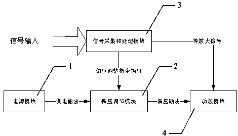
[0019] The method of adjusting the grid bias voltage of the power amplifier on demand to achieve energy saving and consumption reduction, the system composition and principle are as follows figure 1 As shown, it includes a power supply module 1, a bias voltage adjustment module 2, a signal acquisition and processing module 3, and a power amplifier module 4. The specific steps include: the power supply module 1 provides bias voltage adjustment module 2, signal acquisition and processing module 3, and power amplifier module 4. The power supply voltage and bias voltage adjustment module 2 adjust the command output voltage according to the bias voltage of the signal acquisition and processing module 3, and the signal acquisition and processing module 3 couples and collects the signal to be amplified, and calculates the absolute value of the input power value, the difference between the voltage peak and the valley Value and the calculated result is converted into a bias adjustment c...

experiment example 1

[0043]Calculate the efficiency and power consumption of the method described in Example 1, according to the principle of power amplifier, when the input signal is coupled to the input end of the power amplifier tube, its power satisfies the DC calculation principle:

[0044] P = 1 T 0 ∫ T 0 ( A + u ( t ) ) 2 z 0 dt = A 2 z 0 + 1 T 0 ∫ T 0 ...


PUM


Abstract

The invention relates to the field of mobile communication, and discloses a method for adjusting power amplifier grid bias voltage to realize energy conservation and consumption reduction according to requirements, comprising a power supply module, a bias voltage adjusting module, a signal collecting and processing module and a power amplifying module. The method specifically comprises the following steps: supplying power supply voltages for the bias voltage adjusting module, the signal collecting and processing module and the power amplifying module by the power supply module; outputting voltage according to a bias voltage adjusting command of the signal collecting and processing module by the bias voltage adjusting module; coupling and collecting signals to be amplified by the signal collecting and processing module; calculating input power value and absolute value of difference between the voltage wave crest and the voltage wave trough and converting obtained results into the bias voltage adjusting command and transferring the bias voltage adjusting command to the bias voltage adjusting module to perform; and amplifying the power of the signals to the amplified according to the bias voltage output by the bias voltage adjusting module by the power amplifying module. The method has the advantages of fewer calculation steps, stable output and less power consumption, and has higher application value.

Description

technical field [0001] The invention relates to the field of mobile communication, in particular to a method for adjusting the grid bias voltage of a power amplifier on demand to realize energy saving and consumption reduction. Background technique [0002] The main purpose of the invention is to solve the problem that the power consumption of the power amplifier under fixed bias voltage is relatively large when the voltage-controlled power amplifier is in the class A amplification working mode. At home and abroad, there are many solutions to the problem of high power consumption caused by the low efficiency of class A power amplifiers, such as the use of power amplifiers with amplification modes such as class B and class C. But at present, in domestic wireless communication, especially in mobile communication, due to the simple implementation and convenient development of class A amplification, it is very common for the power amplifier module of repeater station to adopt th...

Claims


Application Information

Patent Timeline
IPC IPC(8): G05F1/56
Inventor 赵国谦
Owner 绍兴润煜工程有限公司
Why Eureka
Eureka Blog
Learn More