
Non-contact ultraviolet pulse discharge monitoring device

A non-contact, pulse discharge technology, applied in the direction of testing dielectric strength, etc., can solve the problems of failure to realize safety warning, difficulty in meeting power transmission system, damage to equipment insulation, etc., and achieve the effect of small size, ensuring safety and stability, and high sensitivity

Inactive Publication Date: 2013-11-13
STATE GRID CORP OF CHINA +1
View PDF6 Cites 23 Cited by
  • Summary
  • Abstract
  • Description
  • Claims
  • Application Information

AI Technical Summary

Problems solved by technology

[0002] With the development of the power industry and the increase in the load demand of the power grid, UHV long-distance transmission technology is developing rapidly in my country, and the voltage level is getting higher and higher. The safe operation of high-voltage transmission lines and high-voltage electrical equipment is becoming more and more important. For high-voltage transmission lines As far as the voltage level rises, the safety distance requirements are greater. The traditional method of installing voltage transformers on long poles has been difficult to meet the requirements of the development of power transmission systems. There is an urgent need for a more convenient, safe and efficient power inspection technology. ; For high-voltage electrical equipment, there are various safety monitoring methods, but most of them are real-time monitoring, and safety warning cannot be realized. However, according to the actual working conditions on site, there will be corona discharge phenomenon during the operation of high-voltage electrical equipment. Corona discharge is a low-energy discharge at the beginning. Generally speaking, corona discharge will not cause insulation breakdown quickly. As the discharge increases, it will gradually destroy the insulation of the equipment.

Method used


Image

  • Non-contact ultraviolet pulse discharge monitoring device
  • Non-contact ultraviolet pulse discharge monitoring device

Examples


Embodiment 1

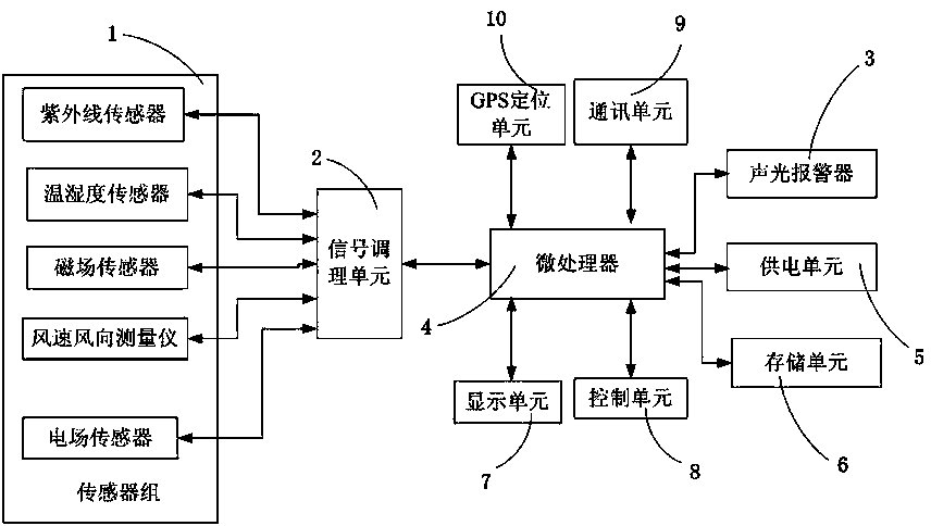
[0022] Such as figure 1 As shown, the non-contact ultraviolet pulse discharge monitoring device includes a sensor 1, a signal conditioning unit 2, and a microprocessor 4 connected in sequence, and the microprocessor 4 is also connected to a power supply unit 5, a storage unit 6, a display unit 7, A control unit 8 , a communication unit 9 , a GPS positioning unit 10 and an audible and visual alarm 3 . Wherein: the above-mentioned sensor 1 includes an ultraviolet sensor, a magnetic field sensor, an electric field sensor, a temperature and humidity sensor and an anemometer; the above-mentioned storage unit 6 is a SD card or IDE memory with a large capacity; the above-mentioned communication unit 9 is a GPRS communication module or 3G communication module; the above-mentioned display unit 7 and control unit 8 are touch display screens. With the popularization of touch display screen equipment, its cost is continuously reduced, and it is also very convenient to use. The touch displ...

Embodiment 2

[0024] On the basis of Embodiment 1, the signal conditioning unit 2 of this embodiment includes a filter circuit, an amplification circuit, and an analog-to-digital conversion circuit connected in sequence, and it is very common in the fields of automatic monitoring and remote control from signal filtering, amplification, and analog-to-digital conversion technology, the specific structure of filter circuit, amplifier circuit and analog-to-digital conversion circuit is no longer repeated in the present embodiment; storage unit 6 adopts IDE memory, that is, the hard disk commonly used in our computer; communication unit 9 adopts the GPRS communication module that model is SIM900A , can also be used in areas not covered by 3G signals, and the SIM900A adopts an industrial standard interface, which can realize the transmission of voice, SMS, data and fax information with low power consumption; the GPS positioning unit 10 adopts a GPS module modeled as SiRF Star III-GPS It has the fu...

Embodiment 3

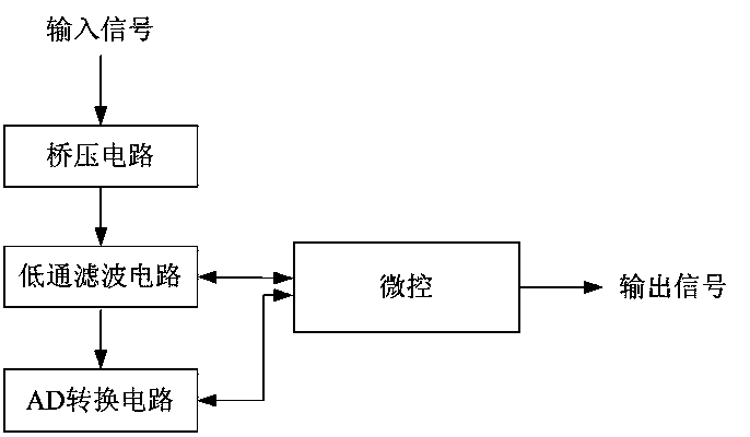
[0026] On the basis of Embodiment 1, the signal conditioning unit 2 in this embodiment includes a bridge voltage circuit, a low-pass filter circuit, and an AD conversion circuit connected in sequence, and a micro-control circuit that is connected with the low-pass filter circuit and the AD conversion circuit at the same time. , the main chips used include: the bridge voltage circuit is provided with a precise 2V reference voltage by REF3220, and the voltage generated by the bridge circuit and the 2V reference voltage are connected to the precision operational amplifier OPA4313, and output to the G pole of the FET through the operational amplifier to generate 2V stable and accurate voltage; the low-pass filter circuit uses the ispPAC20 chip, which consists of two programmable analog macro units (PAC Block), two programmable voltage comparators, an 8-bit D / A converter, configuration memory, and a reference voltage circuit , an automatic calibration unit and an ISP interface circu...


PUM


Abstract

The invention discloses a non-contact ultraviolet pulse discharge monitoring device which comprises a sensor group, a signal conditioning unit connected with the sensor group and a microprocessor connected with the signal conditioning unit, wherein a power supply unit, a memory unit, a display unit, a control unit, a communication unit and a GPS (global positioning system) positioning unit are further connected onto the microprocessor, and the sensor group comprises an ultraviolet sensor. The non-contact ultraviolet pulse discharge monitoring device monitors the discharge conditions by the ultraviolet sensor, performs telecommunication through a communication unit, performs positioning through the GPS positioning unit, and cannot be interfered by high frequency; an further, the discharge can be found out before partial discharge breaks through insulation and damages power equipment, so that alarm can be given in time, measures can be taken, the stability and the safety of a power system are guaranteed, and the non-contact ultraviolet pulse discharge monitoring device has the advantages of high sensitivity, small size, portability and the like.

Description

technical field [0001] The invention relates to the technical field of discharge monitoring of high-voltage transmission lines and high-voltage electrical equipment, in particular to a non-contact ultraviolet pulse discharge monitoring device. Background technique [0002] With the development of the power industry and the increase in the load demand of the power grid, UHV long-distance transmission technology is developing rapidly in my country, and the voltage level is getting higher and higher. The safe operation of high-voltage transmission lines and high-voltage electrical equipment is becoming more and more important. For high-voltage transmission lines As far as the voltage level rises, the safety distance requirements are greater. The traditional method of installing voltage transformers on long poles has been difficult to meet the requirements of the development of power transmission systems. There is an urgent need for a more convenient, safe and efficient power insp...

Claims


Application Information

Patent Timeline
Patent Type & Authority Applications(China)
IPC IPC(8): G01R31/12
Inventor 赵毅余东
Owner STATE GRID CORP OF CHINA
Learn More