
Angle detection device and method based on machine vision

An angle detection and machine vision technology, applied in the field of encoders, can solve the problems of low measurement accuracy and poor anti-pollution ability of magnetic grating rotary encoders

Active Publication Date: 2013-11-13
成都实唯物联网科技有限公司
View PDF5 Cites 14 Cited by
  • Summary
  • Abstract
  • Description
  • Claims
  • Application Information

AI Technical Summary

Problems solved by technology

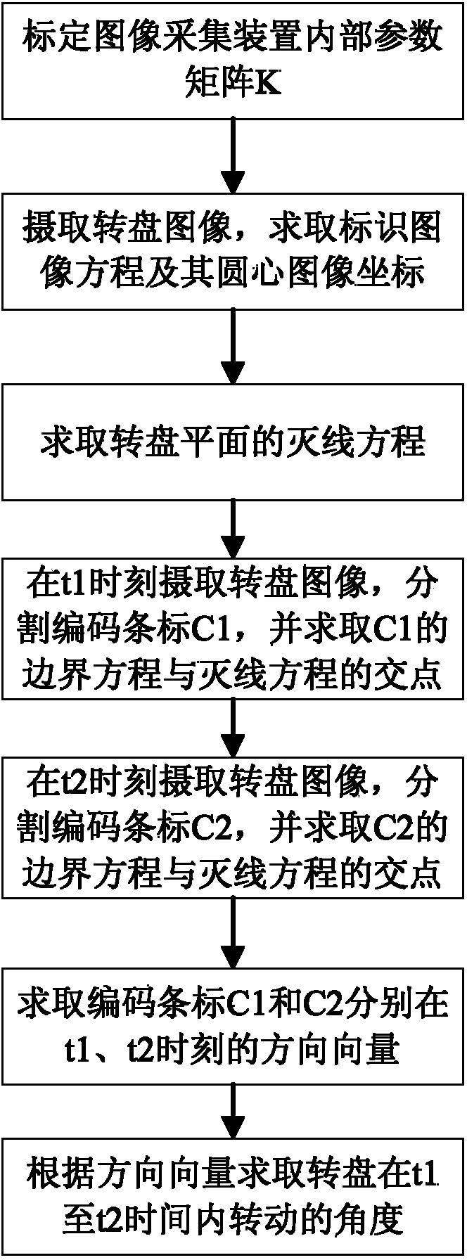
[0003] The purpose of the present invention is to overcome the shortcomings of poor anti-pollution ability of grating rotary encoders and low measurement accuracy of magnetic grating rotary encoders in the prior art, to provide an angle detection device based on machine vision, and to provide a device based on The angle detection method of machine vision improves the anti-pollution ability and impact resistance while realizing accurate detection

Method used


Image

  • Angle detection device and method based on machine vision
  • Angle detection device and method based on machine vision
  • Angle detection device and method based on machine vision

Examples


Embodiment Construction

[0034] The present invention will be further described in detail below in conjunction with test examples and specific embodiments. However, it should not be understood that the scope of the above subject matter of the present invention is limited to the following embodiments, and all technologies realized based on the content of the present invention belong to the scope of the present invention.

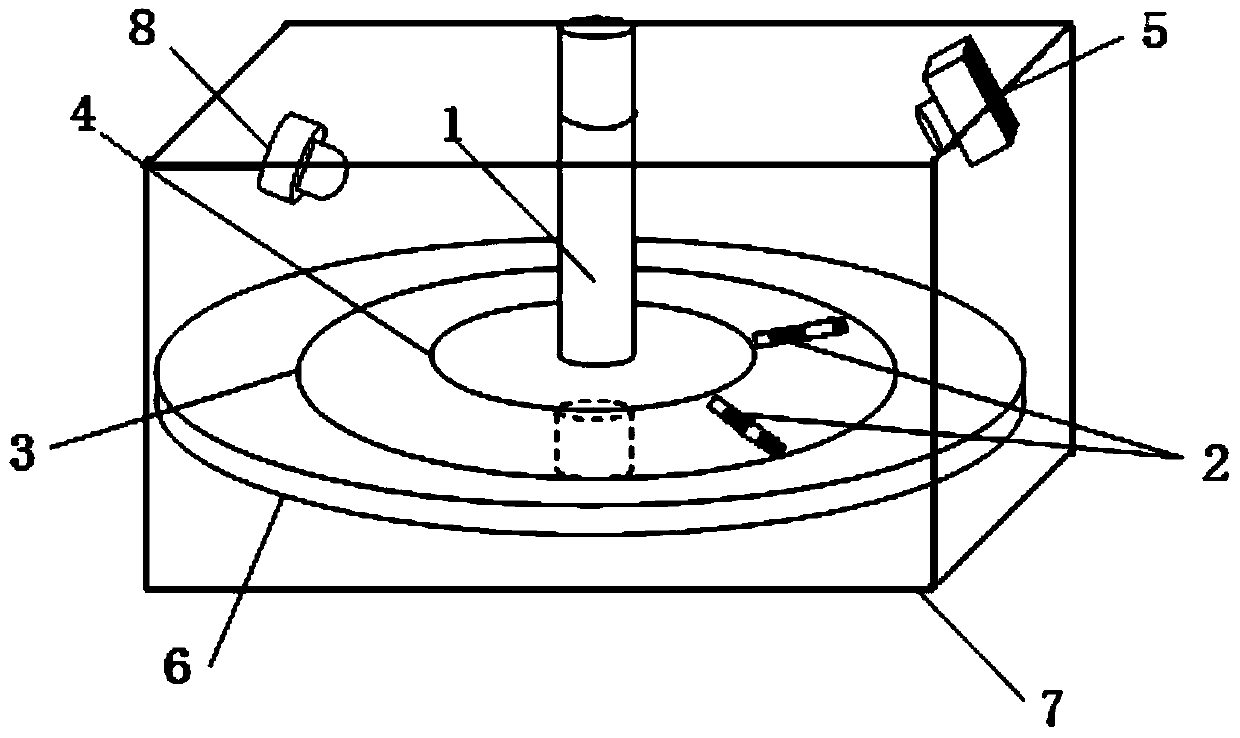
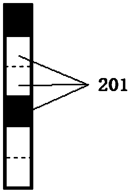
[0035] refer to figure 1, the angle detection device based on machine vision provided by the present invention includes a turntable 6 with a rotating shaft 1 in the center, an outer circle mark 3 and an inner circle mark 4 with the same center but different diameters on the turntable 6, and the outer circle mark 3 The diameter is larger than the inner circle mark 4, and there is at least one coded bar mark 2 between the outer circle mark 3 and the inner circle mark 4, and the center line of each coded bar mark 2 passes through the center of the circle, that is, the center of the turn...


PUM


Abstract

The invention discloses an angle detection device based on machine vision. The angle detection device comprises a casing and a rotary table arranged inside the casing, wherein a rotating shaft is arranged in the center of the rotary table; at least two identifications with same shapes but different sizes are arranged on the rotary table; the at least two identifications are overlapped in centers and are circles, parallelograms, regular triangles or polygons with sides of positive even numbers; at least one encoding strip identification is arranged between the identifications; center lines of encoding strip identifications penetrate through the center; codes corresponding to every two encoding strip identifications are different; and the device further comprises an image acquisition device used for acquiring an image of the rotary table and a lighting source. The invention further provides an angle detection method based on the machine vision at the same time. The angle detection device is simple in structure, high in pollution resistance and higher in impact resistance of the rotary table. According to the angle detection method, detection errors caused by pollutants can be identified and removed through an image processing technology, and the detection accuracy is high.

Description

technical field [0001] The invention relates to the technical field of encoders, in particular to a machine vision-based angle detection device and method. Background technique [0002] The rotary encoder is a device used to measure the rotational speed. It converts mechanical quantities such as angular displacement and angular velocity of the output shaft into corresponding electrical pulses and outputs them in digital quantities. Rotary encoders can be divided into optical grating principle encoders and magnetic magnetic grating principle encoders. The principle of grating The rotary encoder includes a photoelectric code disc with a rotating shaft in the center. There are ring-shaped and dark engraved lines on the photoelectric code disc. A-phase and B-phase pulse signals with phase difference, A-phase and B-phase pulse signals are converted from frequency to voltage to obtain a voltage signal proportional to the rotating shaft speed, and the speed value and displacement ...

Claims


Application Information

Patent Timeline
Patent Type & Authority Applications(China)
IPC IPC(8): G01D5/58G01D21/02
Inventor 王德麾冯军帅宋海亮谢志梅
Owner 成都实唯物联网科技有限公司
Learn More