
Annular seal assembling jig

A technology of annular sealing and assembling fixtures, which is applied in the direction of manufacturing tools, hand-held tools, workpiece clamping devices, etc., can solve the problems of annular sealing rupture and difficulty in assembling spherical bodies, and achieve the effect of preventing rupture and improving yield

Inactive Publication Date: 2013-11-13
HONDA SHUN CO LTD +1
View PDF8 Cites 12 Cited by
  • Summary
  • Abstract
  • Description
  • Claims
  • Application Information

AI Technical Summary

Problems solved by technology

However, annular seals are relatively strong and difficult to assemble in spherical bodies
In addition, when installing, if the annular seal is enlarged too much, the annular seal may be broken

Method used


Image

  • Annular seal assembling jig
  • Annular seal assembling jig
  • Annular seal assembling jig

Examples


Embodiment Construction

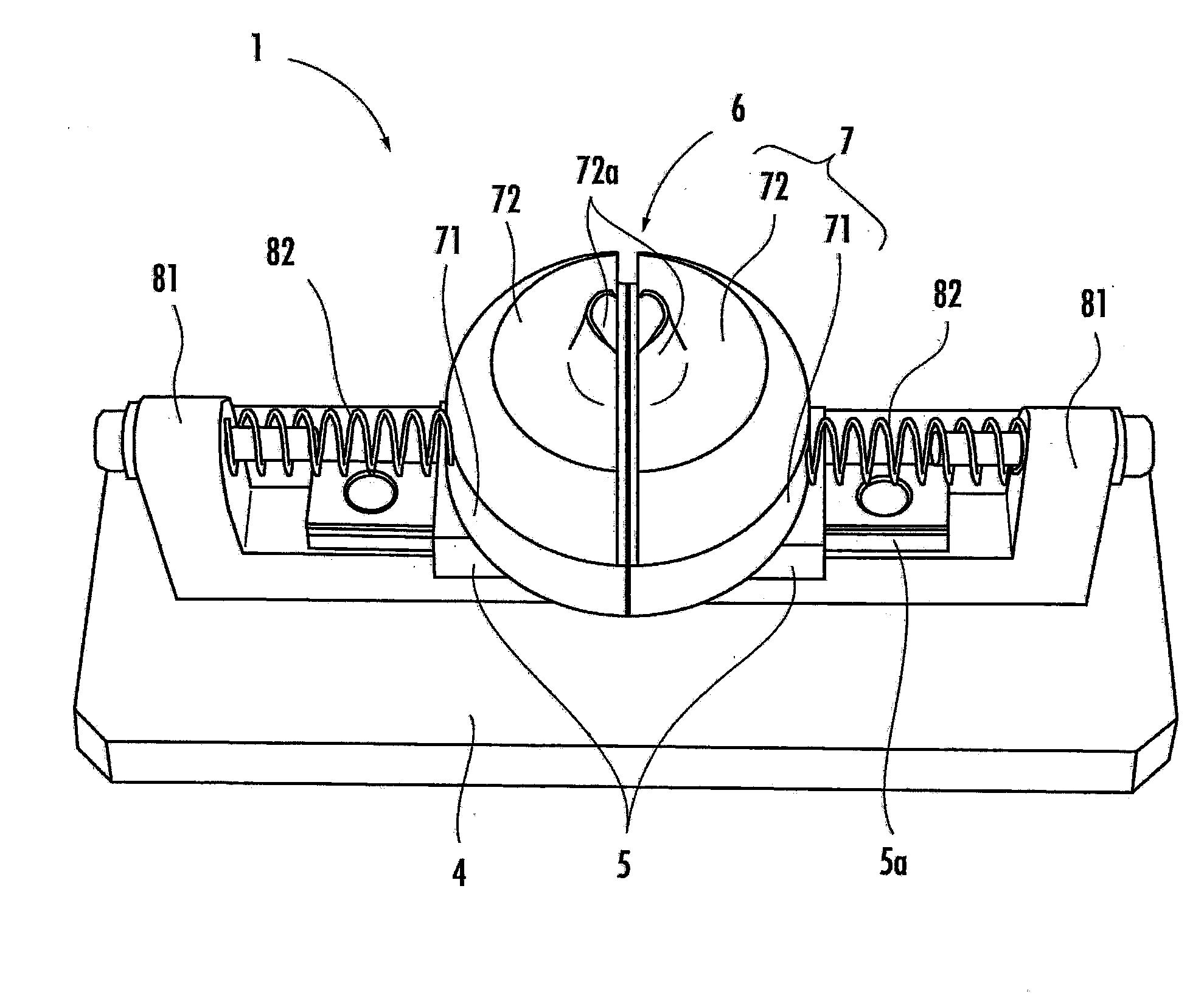
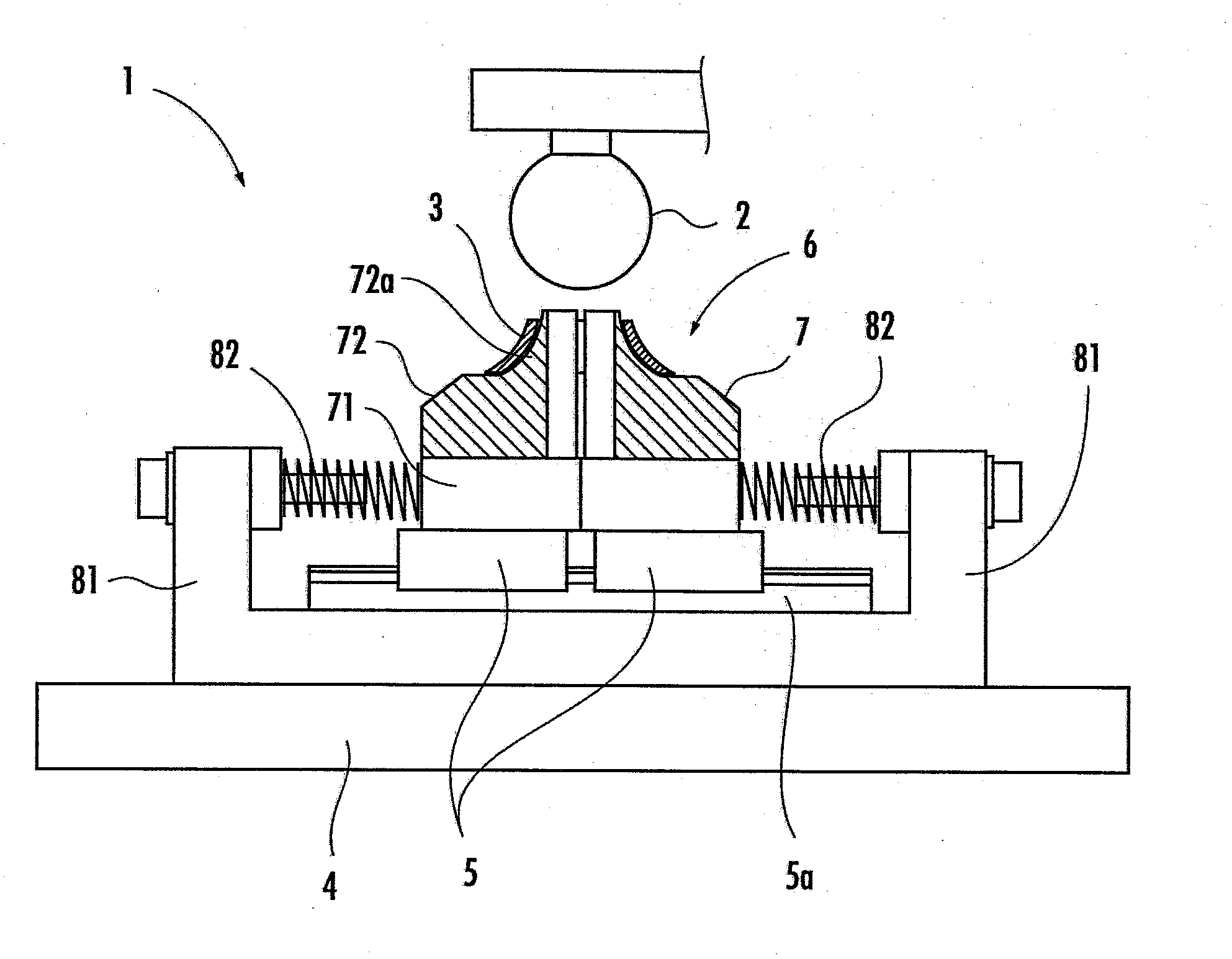
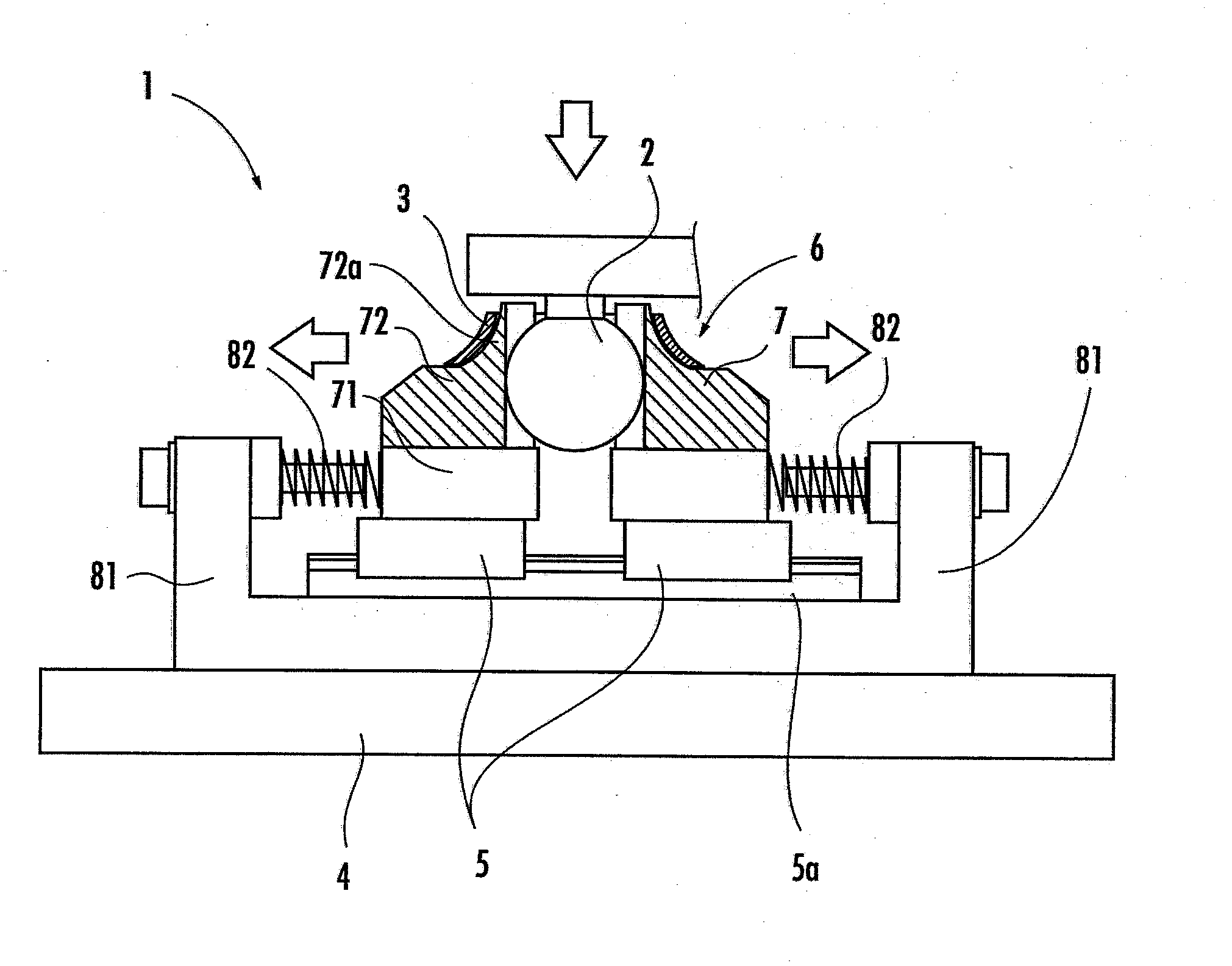
[0029] Reference Figure 1 ~ Figure 4 An embodiment of the ring-shaped seal assembly jig of the present invention will be described. The ring-shaped seal assembly jig 1 of this embodiment is used when assembling the ring-shaped seal 3 to the spherical body 2 of a spherical joint provided on the connecting rod of a pivot assembly (pivot assembly) provided with a wiper link Institutions and so on. The ring-shaped seal assembly jig 1 includes: a base 4; a guide rail 5a arranged on the base 4; and two sliders 5, 5 slidably along the guide rail 5a.

[0030] A semicircular dividing table 7 is attached to each slider 5. A disc-shaped table 6 is formed by bringing two semicircular divided tables 7 into contact with each other, and one annular seal 3 can be placed on the table 6.

[0031] Each dividing table 7 is composed of a semicircular lower part 71 fixed to the slider 5 and a semicircular upper part 72 fixed to the upper surface of the lower part 71. The upper part 72 is made of syn...


PUM


Abstract

An annular seal assembling jig 1 is used when assembling an annular seal 3 to a spherical body 2 of a ball joint. The jig 1 is equipped with a plurality of split tables 7 which constitutes one table 6, a slider 5 fixed to the split table 7 and is capable of sliding freely along a guide rail 5a, a coil spring 82 which biases the slider 5 to the other split table 7 side, and a claw portion 72a provided to each split table 7, so as to catch the annular seal 3 placed on the table 6, from an inner side of the annular seal 3.

Description

Technical field [0001] The present invention relates to a clamp used when assembling a ring seal on a spherical body of a spherical joint. The spherical joint is composed of a spherical body and a spherical recess receiving the spherical body. Background technique [0002] In the prior art, a link mechanism provided on a wiper or the like is known (for example, refer to Japanese Patent Application Laid-Open No. 2005-53443). [0003] The link mechanism has a ball joint. The spherical joint is composed of a spherical body and a spherical recess that receives the spherical body. In addition, in order to prevent water or dust from entering between the spherical body and the spherical concave portion from the outside and causing contamination or rust between the spherical body and the spherical concave portion, an annular seal is assembled on the spherical body. [0004] Summary of the invention [0005] The problem to be solved by the invention [0006] In the past, the ring seal was ma...

Claims


Application Information

Patent Timeline
Patent Type & Authority Applications(China)
IPC IPC(8): B25B11/02B25B27/00
CPCB23P19/04B23P19/084Y10T29/53943Y10T29/53Y10T292/1069
Inventor 森田翔悟
Owner HONDA SHUN CO LTD
Learn More