
Laser processing clamp of medium substrate and application method thereof

A dielectric substrate and laser processing technology, which is applied in the direction of manufacturing tools, laser welding equipment, metal processing equipment, etc., can solve problems such as damage, dielectric substrate damage, and dielectric substrate bending deformation, so as to achieve convenient operation and solve misoperation Accidents, the effect of laser focusing

Active Publication Date: 2013-11-13
CHINA ELECTRONIS TECH INSTR CO LTD
View PDF7 Cites 0 Cited by
  • Summary
  • Abstract
  • Description
  • Claims
  • Application Information

AI Technical Summary

Problems solved by technology

[0008] The technical problem to be solved by the present invention is how to maintain the overall horizontal state of the dielectric substrate during the laser processing process, that is, the bending of the dielectric substrate due to its own weight and the force of the protective nitrogen gas during the downward purge process The technical problem of deformation; and the technical problem of dielectric substrate damage or damage accidents caused by excessive clamping force due to possible misoperation

Method used


Image

  • Laser processing clamp of medium substrate and application method thereof
  • Laser processing clamp of medium substrate and application method thereof
  • Laser processing clamp of medium substrate and application method thereof

Examples


Embodiment Construction

[0033] The dielectric substrate laser processing jig of the present invention will be described in detail below in conjunction with the accompanying drawings.

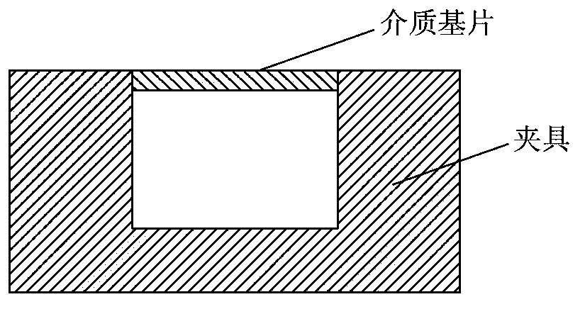
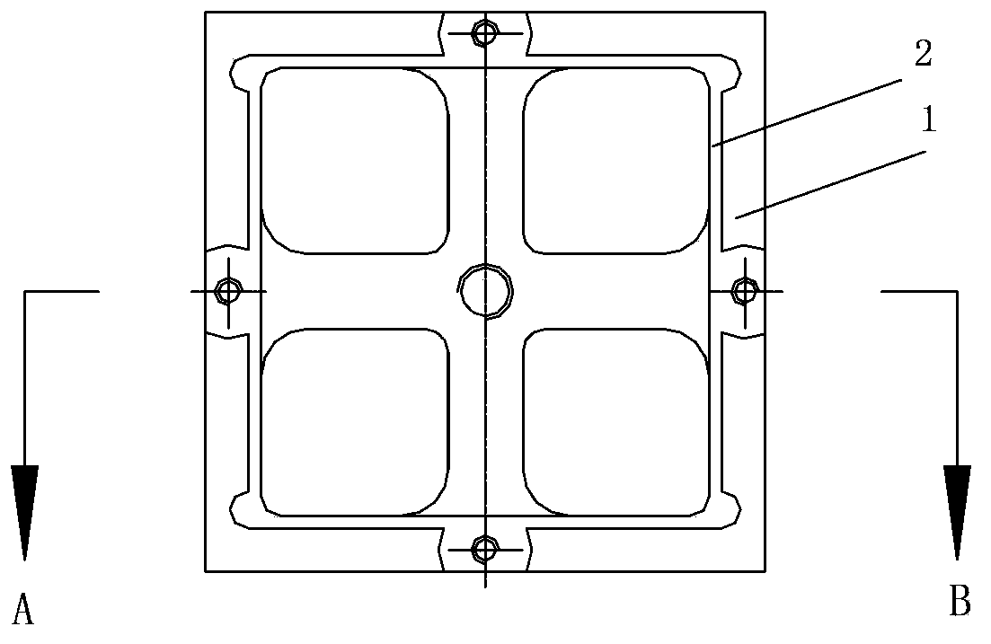
[0034] Such as image 3 As shown, the dielectric substrate laser processing fixture of the present invention includes: the frame is provided with a screw hole 3 for fixing the dielectric substrate, a dielectric substrate 4, and a screw 5 for fixing the dielectric substrate. A recessed rectangular plane area 2, the sunken rectangular plane area 2 is a frame structure in the shape of a "Tian" hollowed out in the middle, and the dielectric substrate 4 is placed in the sunken rectangular plane area 2 with an over-loose fit. The sunken rectangular plane area 2 The depth of the regional depression is equal to the thickness of the dielectric substrate, and the edge of the dielectric substrate is blocked by the head of the dielectric substrate fixing screw 5 .

[0035] Such as Figure 4 As shown, an adjustment screw hole 6 i...


PUM


Abstract

The invention provides a laser processing clamp of a medium substrate and an application method thereof. The laser processing clamp of the medium substrate comprises a frame provided with screw holes for fixing the medium substrate and screws for fixing the medium substrate, wherein a concave rectangular plane region is formed in the middle of the upper surface of the medium substrate and is hollowed to be in a framework structure shaped like a Chinese character 'Tian'; the medium substrate is placed on the concave rectangular plane region; the depth of the concave part of the concave rectangular plane region is equal to or slightly less than the thickness of the medium substrate; the edge of the medium substrate is fixed through the heads of the screws for fixing; the laser processing clamp further comprises at least more than one adjusting screw; a plurality of adjusting screw holes are formed; and the adjusting screws are used for adjusting the levelness of the medium substrate. The invention further discloses the application method of the laser processing clamp of the medium substrate; and the application method comprises the steps of matching and adjusting the screws for fixing the medium substrate and the adjusting screws to enable the medium substrate to be at horizontal and fixed states, and carrying out laser processing under the protection of blowing nitrogen, and the like.

Description

technical field [0001] The invention relates to a laser processing jig, in particular to a dielectric substrate laser processing jig and a using method thereof. Background technique [0002] Microwave and millimeter wave hybrid integrated circuits mostly use hard materials such as ceramic sheets and artificial gemstone sheets as dielectric substrates. The thickness of these substrates is mostly between 0.1mm and 0.7mm. In the process of laser drilling and cutting, in order to To protect the metal layer on the surface of the circuit from oxidation and to remove residues generated during processing in a timely manner, it is usually necessary to use nitrogen purge for protection and substrate residue cleaning. [0003] Due to the low strength of the dielectric substrate, the dielectric substrate is prone to bending and deformation during the nitrogen purging process, which makes the laser processing process prone to inaccurate focusing, which in turn affects the accuracy and qu...

Claims


Application Information

Patent Timeline
Patent Type & Authority Applications(China)
IPC IPC(8): B23K37/04B23K26/42
Inventor 王斌孙立曹乾涛胡莹璐路波
Owner CHINA ELECTRONIS TECH INSTR CO LTD
Learn More