
Illumination driving circuit

A lighting drive and circuit technology, which is applied in lighting devices, lamp circuit layout, electric light sources, etc., can solve the problems of light-emitting diode lamps flickering, unstable, flickering and unstable

Active Publication Date: 2013-11-06
HIMAX ANALOGIC INC
View PDF4 Cites 2 Cited by
  • Summary
  • Abstract
  • Description
  • Claims
  • Application Information

AI Technical Summary

Problems solved by technology

Under the condition of non-conduction, near-conduction or low-voltage operation, affected by the holding leakage current of the silicon-controlled dimmer, the light-emitting diode tube will flicker or be unstable.
Especially when using a general LED driver controller on the market, the above flickering and unstable phenomena will be particularly serious

Method used


Image

  • Illumination driving circuit
  • Illumination driving circuit
  • Illumination driving circuit

Examples


Embodiment Construction

[0040] The following will disclose the spirit of the present invention with illustrations and detailed descriptions. After those skilled in the art understand the embodiments of the present invention, they can be changed and modified by the techniques taught in the present invention without departing from the spirit of the present invention. with range.

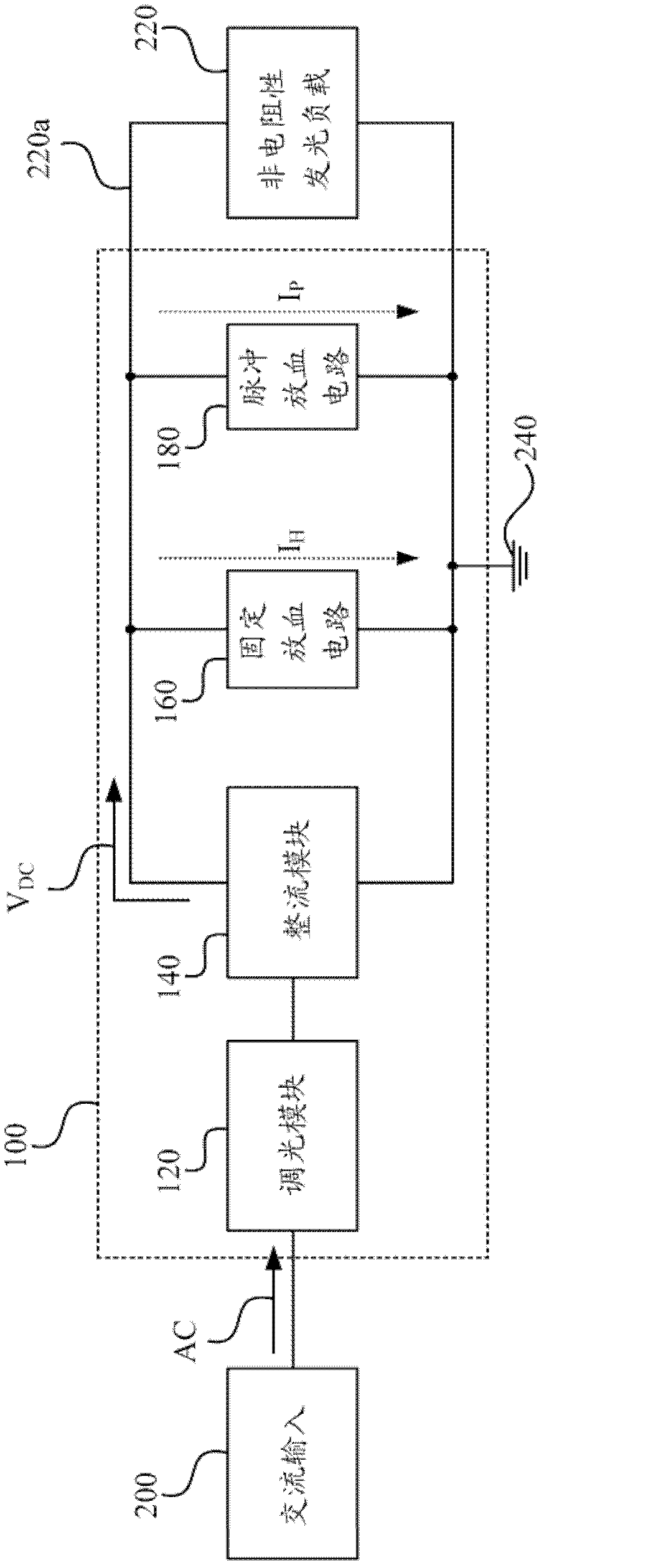
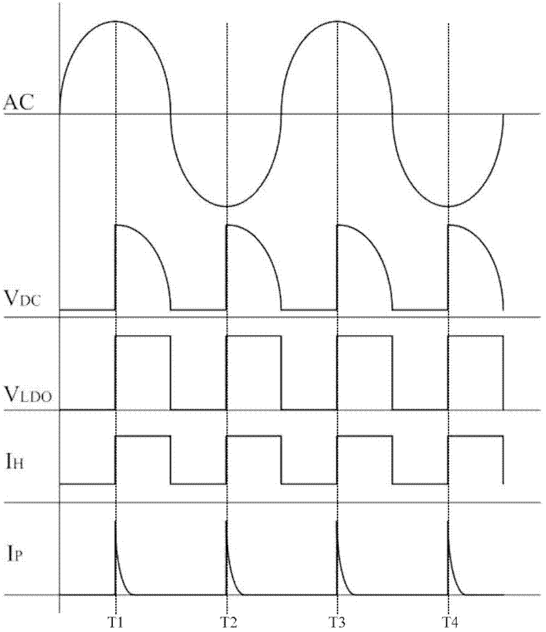
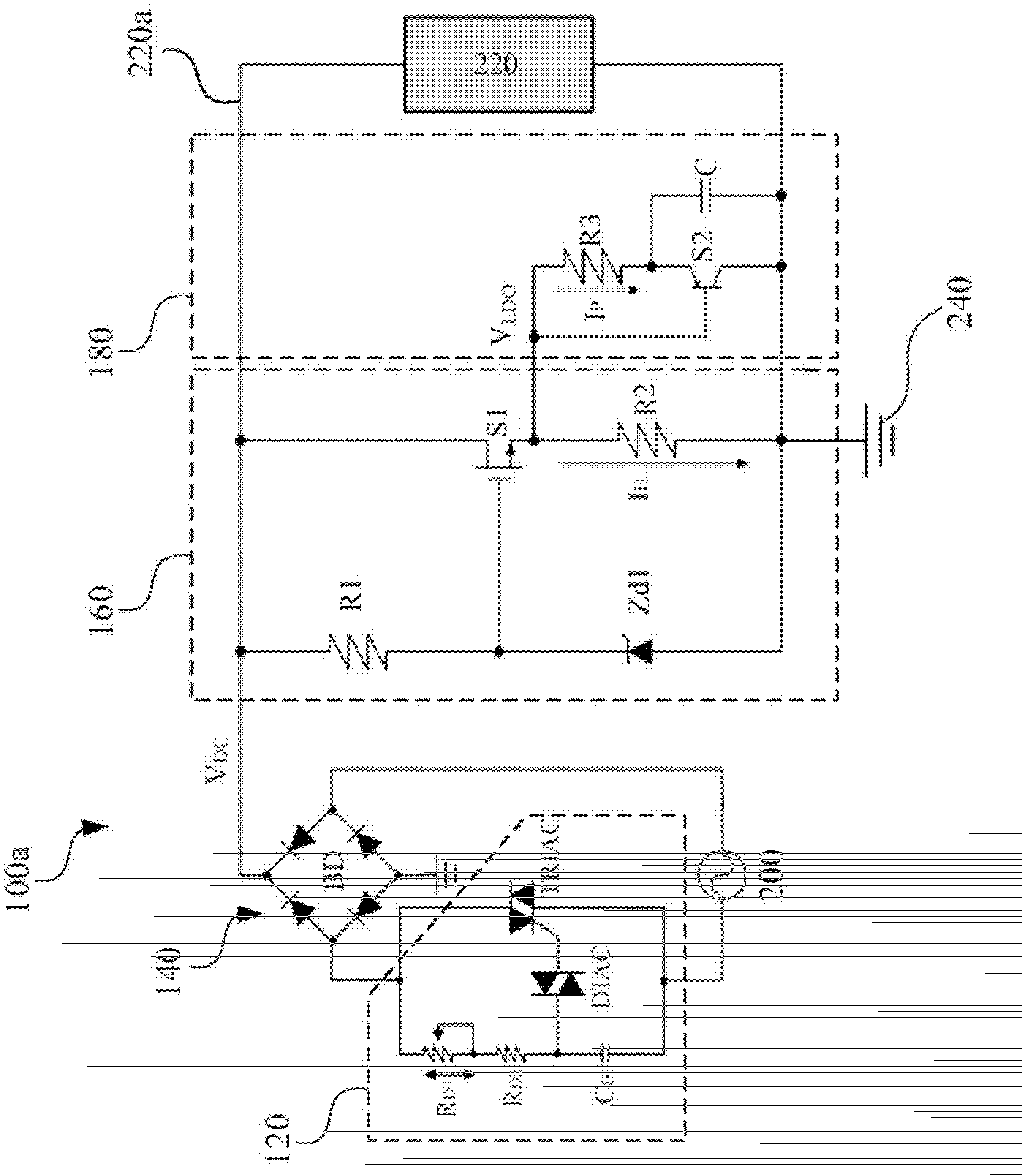
[0041] see figure 1 as well as figure 2 , figure 1 A functional block diagram of an illumination driving circuit 100 according to an embodiment of the present invention is shown. figure 2 A schematic diagram of signal waveforms on the lighting driving circuit 100 according to an embodiment of the present invention is shown. Such as figure 1 As shown, the lighting driving circuit 100 is coupled between the AC input 200 and the non-resistive light-emitting load 220. In practical applications, the non-resistive light-emitting load 220 can be an LED light-emitting element or other equivalent light-emitting elements. The AC...


PUM


Abstract

The invention provides an illumination driving circuit which is coupled between an alternating circuit input and a non-resistiveness light-emitting load. The illumination driving circuit comprises a light-dimmer module, a rectifier module, a fixed leakage circuit and a pulse leakage circuit. The light-dimmer module is coupled with the alternating circuit input to generate a periodical drive signal, and the periodical drive signal comprises a plurality of periodical drive pulses. The rectifier module rectifies the periodical drive signal and sends the rectified periodical drive signal to a positive pole side of the non-resistiveness light-emitting load. The fixed leakage circuit continually draws a continuous leakage current from the positive pole side of the non-resistiveness light-emitting load in the duration of the drive pulses. The pulse leakage circuit transiently draws a pulse leakage current from the positive pole side of the non-resistiveness light-emitting load at trigger time points of the drive pulses.

Description

technical field [0001] The present invention relates to a lighting device, and in particular to a lighting driving circuit on the lighting device. Background technique [0002] In recent years, with the development of optoelectronic technology, many novel lighting devices have been developed in the industry, among which light-emitting diode (Light-Emitting Diode, LED) light tubes have attracted extensive attention. The luminous efficiency of light-emitting diode tubes is better than that of traditional incandescent bulbs, because the waste heat generated by light-emitting diodes, and the photoelectric conversion efficiency is much higher than other types of tubes, which is in line with the trend of energy saving. [0003] Known traditional incandescent light bulbs are resistive loads and are often used with a silicon-controlled dimmer (TRIAC dimmer), which is convenient for users to adjust the required brightness by themselves and avoids waste of electric energy. Generally ...

Claims


Application Information

Patent Timeline
IPC IPC(8): H05B37/02
CPCY02B20/42Y02B20/40
Inventor 范航宇
Owner HIMAX ANALOGIC INC
Learn More