Antenna coil device

一种天线、线圈的技术,应用在天线用线圈设备领域,能够解决侧接线器与天线体导通不良等问题,达到稳定导通的效果

Active Publication Date: 2014-12-24
SUMIDA CORP
View PDF7 Cites 2 Cited by
  • Summary
  • Abstract
  • Description
  • Claims
  • Application Information

AI Technical Summary

Problems solved by technology

As a result, poor conduction between the vehicle side connector and the antenna body may occur

Method used


Image

  • Antenna coil device
  • Antenna coil device
  • Antenna coil device

Examples


Embodiment Construction

[0024] Hereinafter, embodiments of the present invention will be described with reference to the drawings. In addition, in all drawings, the same code|symbol is attached|subjected to the same component, and repeated description is abbreviate|omitted suitably.

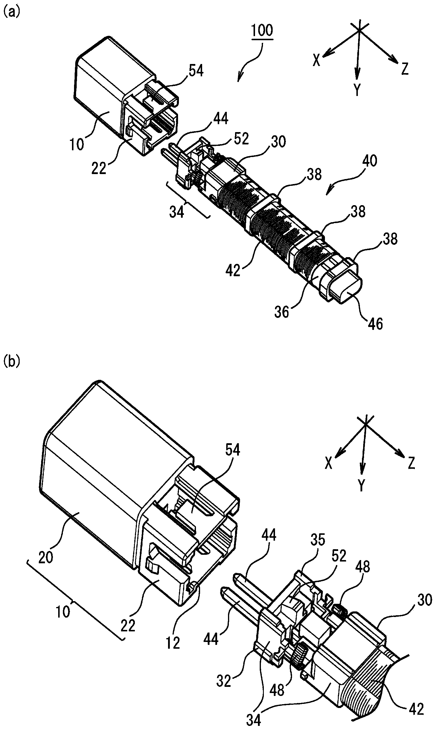
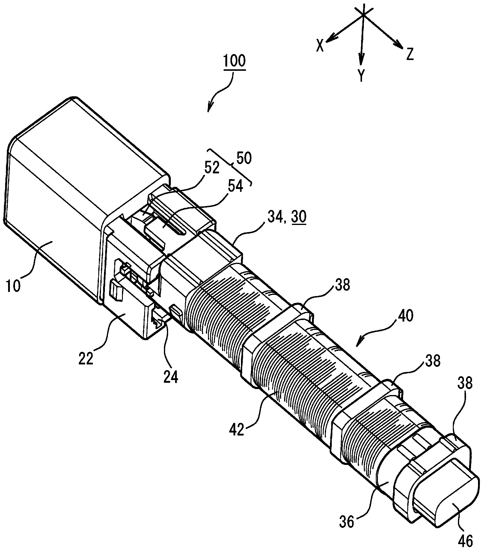
[0025] figure 1 (a) is an exploded perspective view showing the antenna coil device 100 according to the embodiment of the present invention. figure 1 (b) is figure 1 Partial enlarged view of (a). Here, only a portion of the front end side of the base portion 30 is shown, and illustration of other portions is omitted. figure 2 It is a perspective view which shows the coil device 100 for antennas concerning this embodiment. figure 1 and figure 2 Here, the direction of the winding axis of the coil 42 of the antenna body 40 is taken as the Z direction, the direction in which the pair of antenna terminals 44 are arranged is taken as the X direction, and the direction perpendicular to the Z direction and the X directi...


PUM


Abstract

The invention provides an antenna coil device (100) including: a connector unit (10) mounted with a connector of an external circuit detachably by being plugged-in; and a base unit (30) provided with an antenna body (40) including a coil (42), in which the connector unit (10) and the base unit (30) are constituted by separate members and are used by being combined integrally each other, wherein for the connector unit (10) and the base unit (30), there are formed a connector fitting portion (12) and a base fitting portion (32) which are formed with a concave and a convex in a direction intersecting with respect to the plug-in direction of the connector unit (10), and by fitting the connector fitting portion (12) and the base fitting portion (32), the connector unit (10) and the base unit (30) are combined in a state in which the antenna body is positioned with respect to the connector unit (10).

Description

technical field [0001] The present invention relates to a coil device for an antenna. Background technique [0002] In recent years, a smart electronic key system installed in a vehicle and using a coil device for an antenna has been put into practical use. In the smart electronic key system, when the driver holding the electronic key approaches the vehicle and enters the communication range of the system, the antenna coil device communicates with the electronic key, and the control circuit on the vehicle side connected to the antenna coil device is Will allow the driver to unlock the doors and start the engine. In addition, when the driver holding the electronic key is away from the vehicle and comes out of the communication range of the system, the control circuit on the vehicle side will drive the door to lock again. [0003] Japanese Patent Document 1 and Patent Document 2 clearly describe such an antenna coil device. In the antenna coil device of Japanese Patent Docu...

Claims


Application Information

Patent Timeline
Patent Type & Authority Applications(China)
IPC IPC(8): H01Q7/02
CPCH01R13/506H01Q1/1207H01Q1/362H01Q11/08H01Q7/00H01Q1/3241H01Q1/3233
Inventor 马原繁
Owner SUMIDA CORP
Why Eureka
Try Eureka