
Interface circuit for connecting a microphone circuit to a preamplifier.

A technology of preamplifier and interface circuit, applied in the field of interface circuit, can solve the problem that the occupied area cannot be reduced below the expected value, etc.

Inactive Publication Date: 2013-10-30
ST ERICSSON SA
View PDF5 Cites 14 Cited by
  • Summary
  • Abstract
  • Description
  • Claims
  • Application Information

AI Technical Summary

Problems solved by technology

[0009] In view of the above limitations of prior art interface circuits between a microphone circuit and a preamplifier, it is an object of the present invention to provide an interface circuit for connecting a microphone circuit to a preamplifier, which is adapted to address the above Shown about the inability to reduce the footprint below the desired value due to the presence of one or more decoupling capacitors that cannot be integrated on a chip

Method used


Image

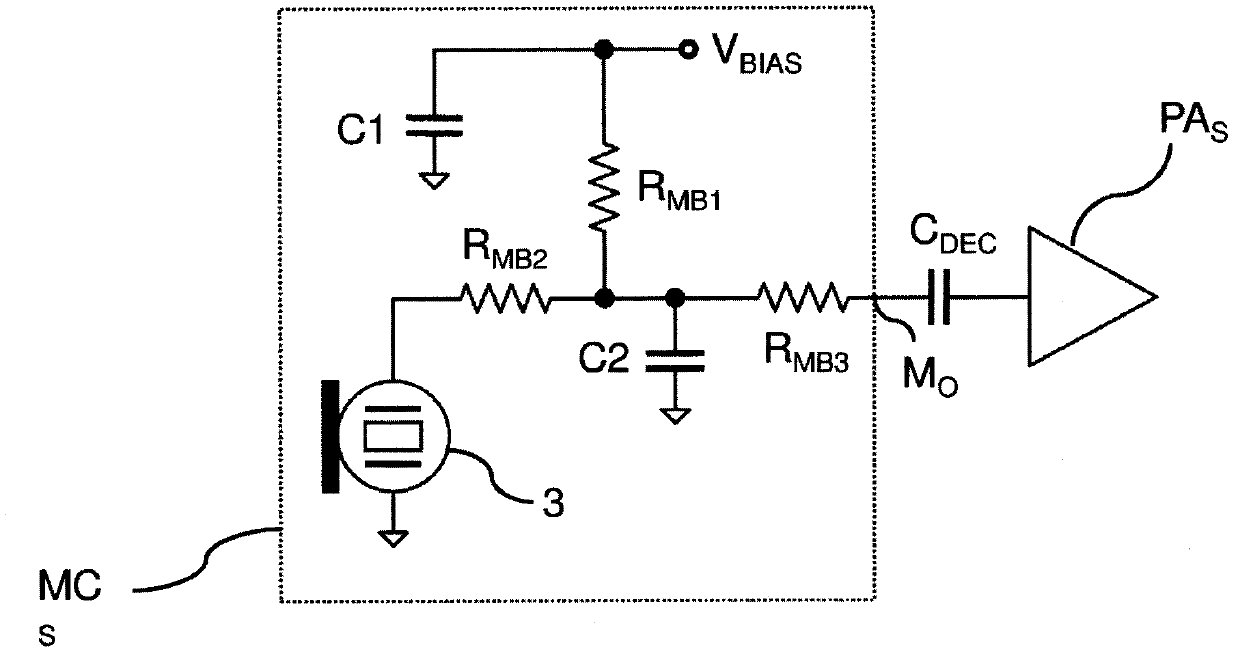
  • Interface circuit for connecting a microphone circuit to a preamplifier.
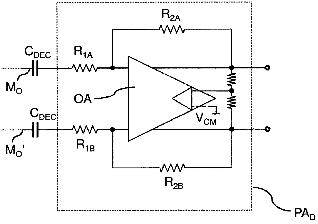
  • Interface circuit for connecting a microphone circuit to a preamplifier.
  • Interface circuit for connecting a microphone circuit to a preamplifier.

Examples


Embodiment Construction

[0027] In the drawings, the same reference numerals / symbols will be used to designate the same or similar elements.

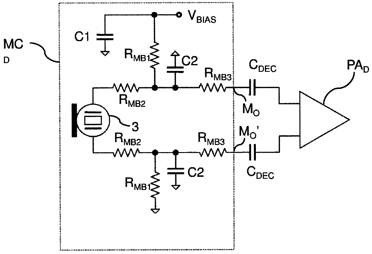
[0028] Figure 5 shown including the microphone circuit MC D A very schematic view of an embodiment of a mobile terminal 5 such as a mobile phone 5 . According to one embodiment, and without introducing any limitations for this reason, the microphone circuit MC D can be used with the differential microphone circuit MC represented in Figure 2 D resemblance. Microphone circuit MC DIt includes a microphone 3, a bias network for the microphone and two differential output nodes Mo, Mo'. According to one embodiment, the bias network of the microphone may be the same or similar to the known bias network of FIG. 2 .

[0029] The mobile phone 5 includes a circuit board 6 including an integrated microphone preamplifier circuit 60 . According to the illustrated embodiment, the circuit board 6 further comprises an analog-to-digital converter 70 and a digital audio pr...


PUM


Abstract

An interface circuit (INT C ) is disclosed, adapted to connect a microphone circuit (MC D ) to a preamplifier (P A ), the microphone circuit (MC D ) comprising a microphone (3) and at least an output node (M O , M O ') and the preamplifier (P A ) comprising at least an input node (10, 10') adapted to be connected to said output node (M O , M O ') through said interface circuit (INT C ). The interface circuit (INT C ) comprises at least a decoupling capacitor (C DEC ) for DC decoupling said input node (10, 10') from said output node (M O , M O '), the decoupling capacitor (C DEC ) having a first end connected / connectable to said input node (10, 10') and a second end connected / connectable to said output node (M O , M O '). The interface circuit (INT C ) comprises at least one active circuit (UG AMP , UG AMP ') connected to the first end of the decoupling capacitor (C DEC ), adapted to operatively act as a resistance multiplier and having an equivalent resistance that together with the decoupling capacitor (C DEC ) defines a high-pass filter operatively connected / connectable between the microphone (3) and the preamplifier (P A ) .

Description

technical field [0001] The invention relates to an interface circuit for connecting a microphone circuit to a preamplifier. Background technique [0002] One of the main aspects taken into consideration in the development of electronic devices, especially mobile devices, is footprint. In the field of mobile devices such as mobile phones, one of the keys to creating a phone with more functionality without changing the size of the phone is reducing the footprint on a printed circuit board (PCB). For many years, the focus has been on integrating as much as possible on-chip all those passive components that represent the main limitation of area reduction, such as resistors, capacitors and inductors. In older generation phones, this component was an SMD (Surface Mount Device) mounted directly on the motherboard. Later, due to advances in technology, these devices were located inside the chip package, known as the PDI (Passive Device Integration) approach, and in some cases dire...

Claims


Application Information

Patent Timeline
IPC IPC(8): H03H11/46H03H5/12
CPCH04R3/00H03H5/12H03H11/46
Inventor 安德烈亚·巴尔别里杰尔马诺·尼科利尼
Owner ST ERICSSON SA
Learn More