
Hand-power tool with a reduction gear

一种手持式工具机、减速装置的技术,应用在传动装置、制造工具、轻便机动装置等方向,能够解决部件故障、部件负载等问题

Active Publication Date: 2013-10-30
ROBERT BOSCH GMBH
View PDF6 Cites 5 Cited by
  • Summary
  • Abstract
  • Description
  • Claims
  • Application Information

AI Technical Summary

Problems solved by technology

This can cause shock-like loads on the components associated with the drive train of the cordless drill screwdriver and lead to failure of the components contained in the drive train

Method used


Image

  • Hand-power tool with a reduction gear
  • Hand-power tool with a reduction gear
  • Hand-power tool with a reduction gear

Examples


Embodiment approach

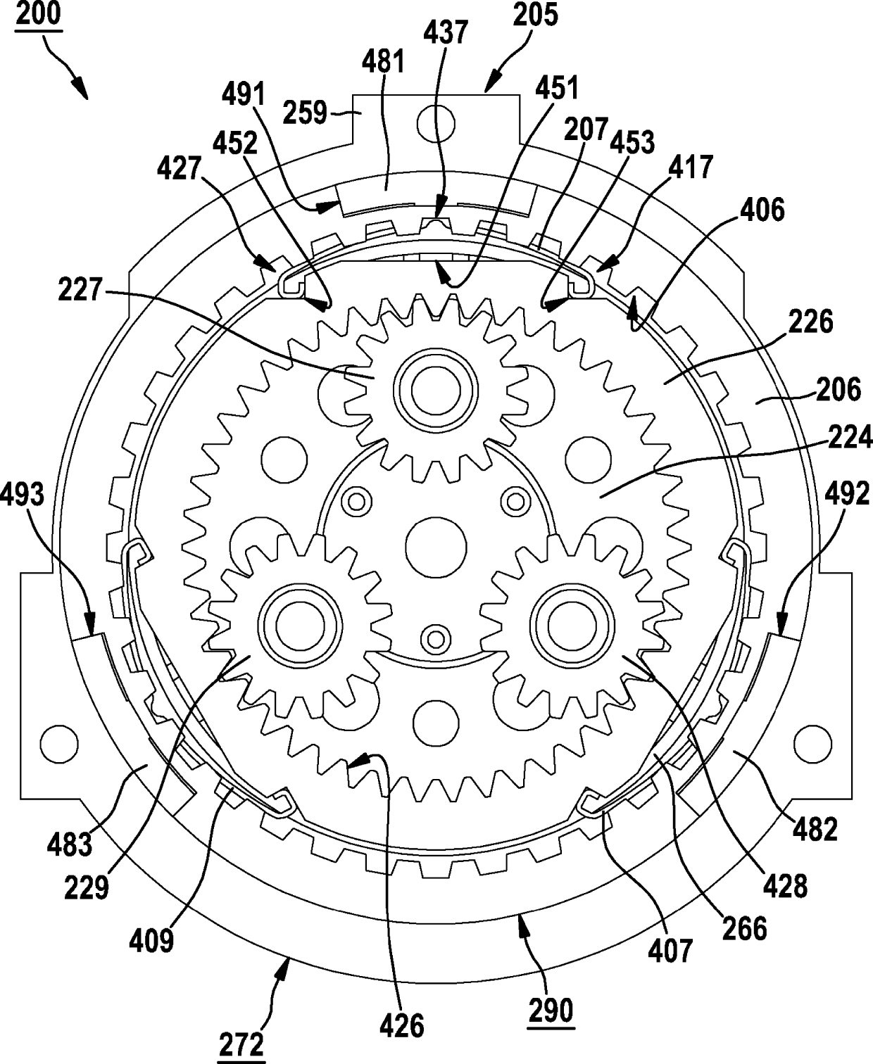
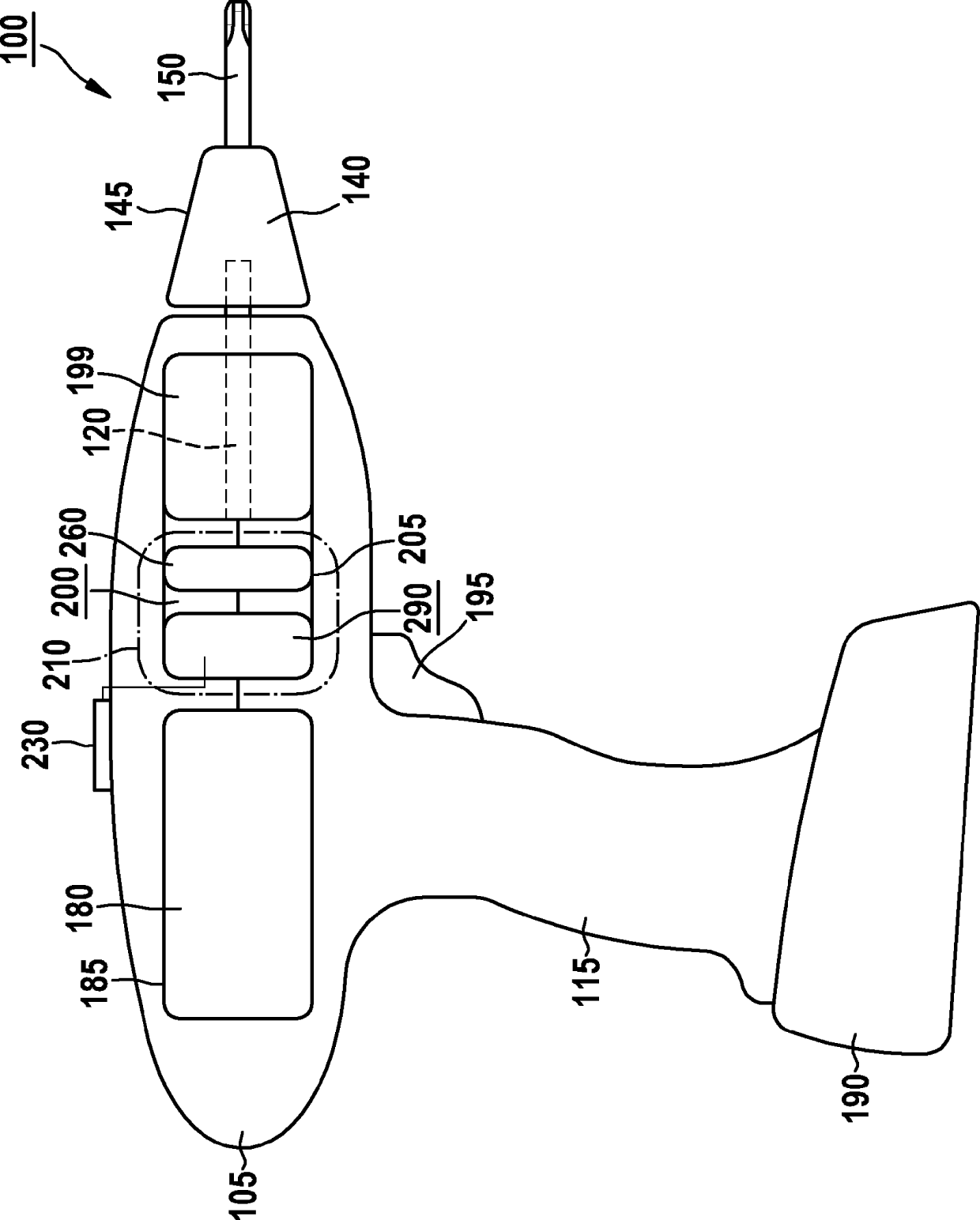
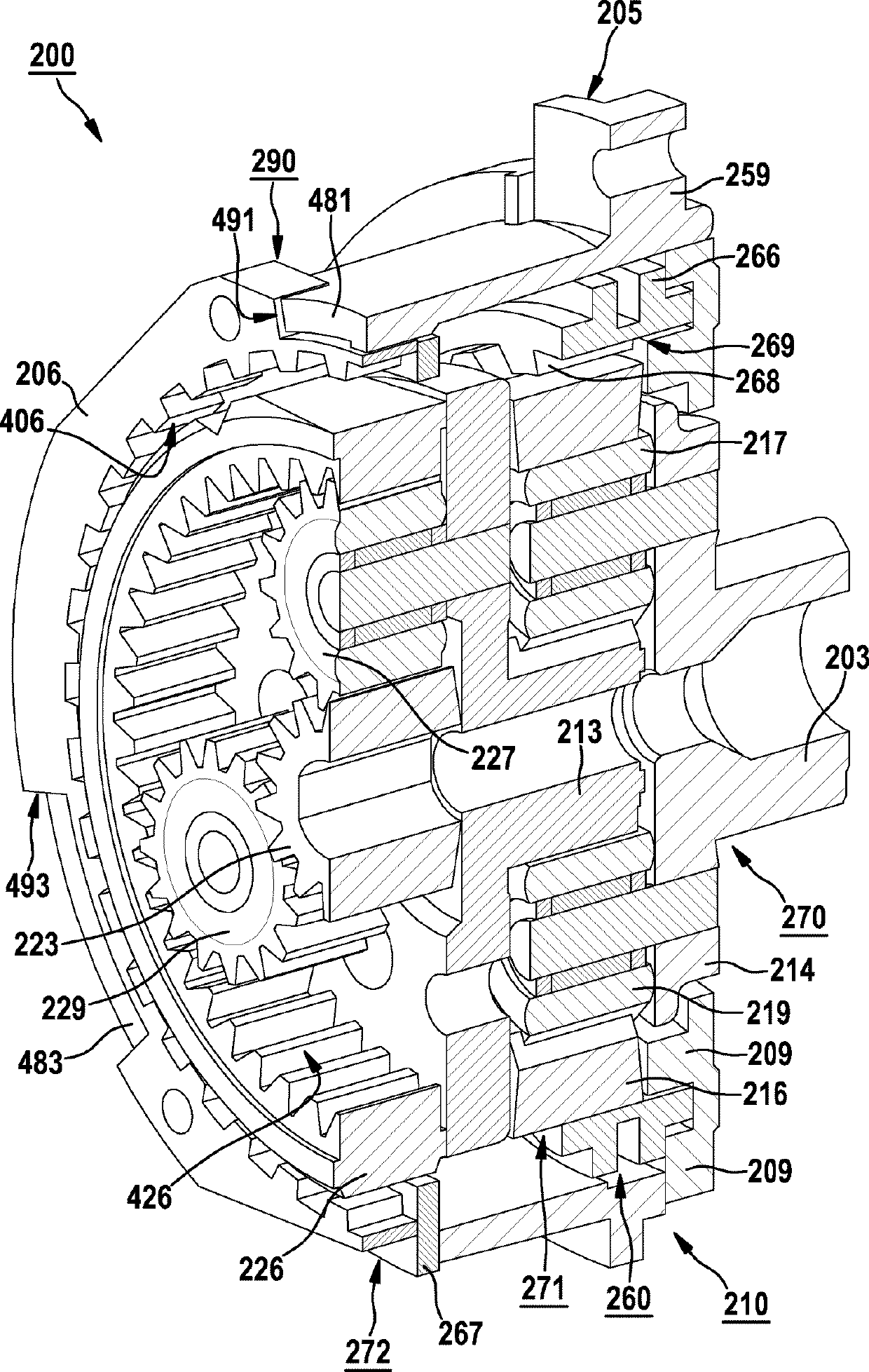
[0030] According to one specific embodiment, the transmission 200 is a reduction gear, for example a planetary gear having different planetary gear stages, which is optionally equipped with a torque clutch 199 . Torque clutch 199 is designed to prevent passing through the reduction gear during operation of hand power tool 100 if the torque transmitted by drive shaft 120 to reduction gear 200 exceeds a threshold value adjustable by the user of hand power tool 100 . 200 drives the transmission shaft 120 .

[0031] In addition, the speed reduction device 200 is equipped with a shift mechanism 260 that can be manipulated by the equipped operating element 230, so that the speed reduction device 200 can be at least in the first gear with a relatively high torque and in the second gear with a relatively low torque. Switch between gears. During operation of hand-held power tool 100 , reduction gear 200 is rotationally driven by drive motor 180 . Below the reduction gear 200 , which ...


PUM


Abstract

The invention relates to a hand-power tool (100) with a reduction gear (200) that can be driven by a motor (180) in order to drive a driveshaft (120), said reduction gear (200) lying in a transmission housing (205) and being shiftable at least between a first gear with comparatively high torque and a second gear with comparatively low torque via a gear shifting system (230, 260). The reduction gear (200) is associated with a mechanical overload protection device (290) that is designed to limit the reduction gear (200) during the operation of the hand-power tool (100) if a torque that is transferred from the driveshaft (120) onto the reduction gear (200) exceeds a machine-specific threshold.

Description

technical field [0001] The invention relates to a hand-held power tool with a motor-driven reduction gear for driving a transmission shaft, wherein the reduction gear is arranged in the transmission housing and can be used at least in relatively small A shift is made between a high torque first gear and a relatively low torque second gear. Background technique [0002] Hand-held power tools of this type are known from the prior art, which have a reduction gear for driving the drive shaft, with which a predetermined motor speed can be reduced to the speed range of the drive shaft required for the respective application middle. For example, in battery-powered screwdrivers, cordless screwdrivers and / or battery-powered percussion drills, the motor speed of approximately 20,000 U / min is reduced to a speed range of approximately 150 to 2000 U / min. The reduction gear is designed, for example, as a multi-stage planetary gear with at least two gears, so that a user of such a hand-h...

Claims


Application Information

Patent Timeline
Patent Type & Authority Applications(China)
IPC IPC(8): B25F5/00
CPCB25F5/001F16D7/00F16H3/62
Inventor R.温德沙伊默H.勒姆
Owner ROBERT BOSCH GMBH
Learn More