
fluid exciter

A vibration exciter and fluid technology, applied in the direction of fluid using vibration, can solve the problems of short service life, discontinuous excitation force, and applicability constraints, so as to solve the problem of insufficient excitation force and increase the energy conversion rate. , the effect of reducing water resistance

Active Publication Date: 2018-10-23
SHANGHAI JIAOTONG UNIV
View PDF10 Cites 0 Cited by
  • Summary
  • Abstract
  • Description
  • Claims
  • Application Information

AI Technical Summary

Problems solved by technology

The main shortcomings of the electric vibrator are: 1) Due to the particularity of the structure of the electric vibrator itself, its energy consumption is relatively high and its service life is relatively short. , Leakage and other faults will cause the electric vibrator to burn out, cause losses, affect production and cause safety accidents; 2) It is only suitable for dry environments, and its use is relatively single
However, the main disadvantages of this technology are: 1) the motion of the vibrating ball in the cavity is not stable, and it cannot provide a stable excitation force; 2) when the gas flow rate is small, it is not enough to push the vibrating ball to roll, and the device cannot work normally Provide exciting force; 3) The driving force can only be gas, and the applicability is restricted. For example, in underwater operations, the high water pressure under water leads to insufficient air pressure and cannot produce good vibration effects
The main problems of this technology are: 1) the excitation force is not generated continuously, which is not suitable for general working conditions; 2) the adjustment of the excitation force is inconvenient and the vibration force is relatively small, and the period required to change the excitation force is long, and the force The response lags seriously; 3) The structure of the device is complex and heavy, it is extremely inconvenient to install and debug, and the conditions of use are quite limited
[0006] As the vibrating machinery industry has higher and higher requirements for product safety and energy saving, and the application range of the industry is becoming wider and wider, the existing vibrators are not enough to meet the requirements of high vibration times, light weight, adjustable, and wide application conditions.

Method used


Image

  • fluid exciter
  • fluid exciter
  • fluid exciter

Examples


Embodiment 1

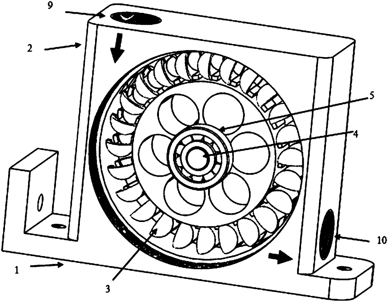
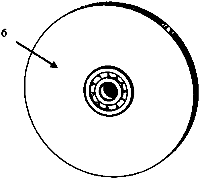
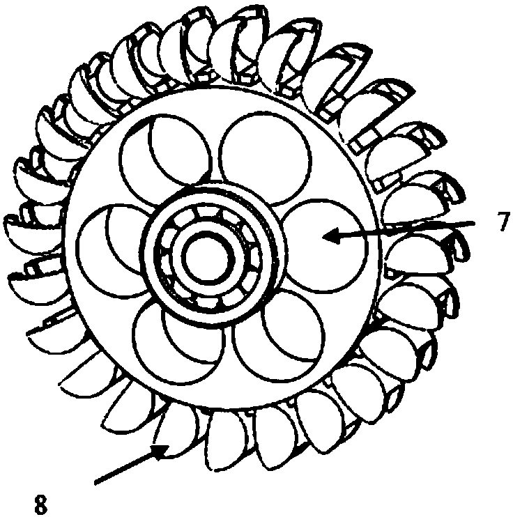
[0032] Such as Figure 1-3 As shown, for a water pressure of 1Mpa, this embodiment provides a fluid exciter with strong exciting force, convenient and durable, consisting of a base 1, a housing 2, an exciting element 3, an optical axis 4, a waterproof bearing 5, Cavity cover plate 6, eccentric vibrator 7, turbine blade 8, water inlet 9 and water outlet 10, wherein:

[0033] The base 1 and the housing 2 arranged on the base 1 form an integral structure, which is rigid, dense and high in strength, and can be fixed by screws passing through the horizontal and vertical plate holes on both sides of the base;

[0034] The middle part of the housing 2 is provided with a cylindrical cavity, and the upper part of the housing 2 is provided with a water inlet 9 along the tangential direction; the water outlet 10 is provided on the center line of the bottom of the right side plate of the housing 2;

[0035] The excitation element 3 is composed of an eccentric vibrator 7 and a turbine bla...

Embodiment 2

[0050] Such as Figure 1-3 As shown, for a water pressure of 1Mpa, this embodiment provides a fluid exciter with strong exciting force, convenient and durable, consisting of a base 1, a housing 2, an exciting element 3, an optical axis 4, a waterproof bearing 5, The cavity cover plate 6, the eccentric vibrator 7, the turbine blade 8, the water inlet 9 and the water outlet 10 are composed, and the assembly method of each component is the same as that described in the first embodiment.

[0051] In this embodiment, the size of the base 1 is: 80*45*10mm, and it is connected with the housing 2 to form a whole.

[0052] In this embodiment, the size of the housing 2 is: length*width*height=45*45*45mm; the upper part of the water inlet 9 on the top of the housing 2 is an M20 threaded hole, and 4 water supply pipes are externally connected through quick connectors; The size of the rectangular opening at the lower part of the housing 2 is length*width=12*3mm; the water outlet 10 on the...


PUM


Abstract

The invention provides a fluid vibration exciter. The fluid vibration exciter comprises a base, a shell, a vibration excitation element, a polished shaft, waterproof bearings and cavity cover plates, wherein the base and the shell are integrated; a cylindrical cavity is formed in the shell; the axis of the cavity is a horizontal line; the vibration excitation element is placed in the cavity; a water inlet is formed in the vertical tangential direction of the cavity, and the side face of the shell is provided with a water outlet; the vibration excitation element comprises a cylindrical hollow centrifugal vibrator; the axis of the centrifugal vibrator coincides with the axis of the cavity; blades are evenly distributed on the side face of the circumference of the vibration excitation element; the polished shaft penetrates through a center hole of the centrifugal vibrator, and the two ends of the polished shaft are inserted into inner holes of the waterproof bearings; the waterproof bearings are mounted in bearing grooves formed in the cavity cover plates and can rotate in a friction-free mode. The fluid vibration exciter is simple in overall structure, convenient to manufacture, easy to mount and dismount, capable of being fixed to a horizontal plane or a vertical plane, high in excitation force, wide in application range and especially suitable for vibration operation in underwater environments, driving media are diversified, and materials are durable.

Description

technical field [0001] The invention relates to a vibration exciter, in particular to a device which utilizes the impact of high-speed fluid to generate vibration. Background technique [0002] Today, vibrators are widely used in various industries such as hopper emptying, material screening, concrete compaction and sand and any other powder processing, pipeline transportation and other industries. According to the energy consumption form and working principle of the vibrator, there are mainly electric vibrators (rotary, linear, magnetic), hydraulic vibrators, and pneumatic vibrators (rotary, linear). The electric vibrator uses a motor to drive a group of eccentric blocks at the ends of the two shafts to generate vibration force. It is specially designed for high-frequency, high-temperature and explosion-proof fields; the pneumatic vibrator is mainly composed of a seat, a cover, an unbalanced rotor, and bearings. , the rolling bearing is pressed into the bearing chamber, th...

Claims


Application Information

Patent Timeline
Patent Type & Authority Patents(China)
IPC IPC(8): B06B1/18
CPCB06B1/186
Inventor 喻国良祝文龙张民曦王闻恺
Owner SHANGHAI JIAOTONG UNIV
Learn More