Signal generating circuit for real-time clock device and related method

A signal generation circuit and real-time clock technology, applied in the direction of generating electrical pulses, pulse generation, electrical components, etc., can solve problems such as long start-up time, unstable operation, output wrong clock signals, etc., to achieve energy saving and strong anti-noise ability, effect of environmentally friendly energy

Inactive Publication Date: 2013-10-30
世芯电子(上海)有限公司
View PDF4 Cites 2 Cited by
  • Summary
  • Abstract
  • Description
  • Claims
  • Application Information

AI Technical Summary

Problems solved by technology

However, when the signal generating circuit operates with a lower voltage or current, it often has a long start-up time or unstable operation due to noise, thus outputting a wrong clock signal, so that the real-time clock device cannot output the correct time. , doesn't even work
[0005] In addition, when the signal generation circuit operates at a lower voltage or current, it is easy to cause unstable operation due to noise and require multiple restarts. Generally, only a simple resistor-capacitor circuit (RC circuit) is used to generate a power supply reset signal. In this way, the power supply reset signal cannot be generated at an appropriate time, and other circuits of the real-time clock device cannot be reset in a timely manner, thus causing the real-time clock device to fail to operate normally

Method used


Image

  • Signal generating circuit for real-time clock device and related method
  • Signal generating circuit for real-time clock device and related method
  • Signal generating circuit for real-time clock device and related method

Examples


Embodiment Construction

[0015] Embodiments of the present invention will be described below in conjunction with related drawings. In these drawings, the same reference numerals represent the same or similar elements, procedures or steps.

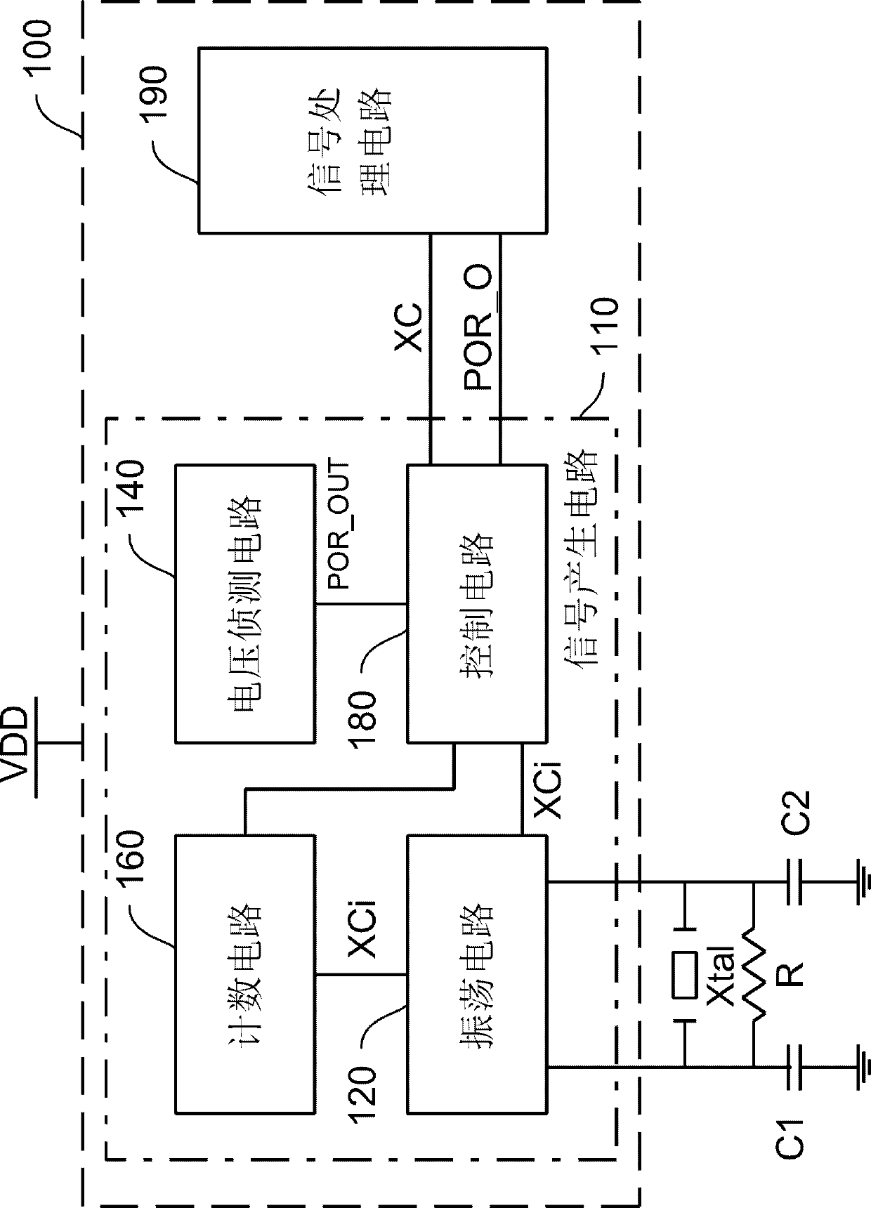
[0016] figure 1 It is a simplified functional block diagram of the real-time clock device 100 according to an embodiment of the present invention. For the convenience of description, figure 1 Other elements and connection relationships are omitted in . The real-time clock device 100 includes a signal generating circuit 110 and a signal processing circuit 190 , and the real-time clock device 100 is coupled to a voltage VDD. The signal generation circuit 110 includes an oscillation circuit 120 , a voltage detection circuit 140 , a counting circuit 160 , and a control circuit 180 . The signal generation circuit 110 is used to generate the clock signal XC and the reset signal POR_O, and output them to the signal processing circuit 190, so that the signal processing c...


PUM


Abstract

The invention provides a signal generating circuit for a real-time clock device, and the signal generating circuit includes an oscillation circuit, a voltage detecting circuit and a control circuit. The oscillation circuit is used for generating an oscillating signal, and the voltage detecting circuit is used for detecting voltage coupled by a signal generating circuit. The control circuit is coupled to the voltage detection circuit and a counting circuit. When the voltage detected by the voltage detection circuit is within a preset voltage range, the control circuit sets the oscillation circuit for the first time to generate an oscillation signal with a larger current, sets the oscillation circuit for the second time to generate an oscillating signal with a smaller current, and generates a clock signal for the third time based on the oscillating signal. The signal generating circuit can not only reduce power consumption, but can also enables the signal generating circuit to be less susceptible to noise in a low power state with stronger resistance to noise. Therefore, the real-time clock device can still be capable of normal operation in a low power state, even if there are noises.

Description

technical field [0001] The invention relates to a real-time clock device, in particular to a signal generating circuit of the real-time clock device. Background technique [0002] A real time clock can output a signal representing the current time (hereinafter referred to as real time), and has advantages such as low power consumption, so it is widely used in electronic devices such as computers, digital cameras, and mobile phones. [0003] The real-time clock device needs to provide various required signals according to the signal generating circuit, so as to calculate the actual time correctly. For example, the signal generating circuit can generate a 32.768KHz oscillating signal (that is, oscillating 215 times per second) as a clock signal to output to the signal processing circuit to calculate the actual time. The signal generation circuit can also generate a power on reset signal (power on reset, POR), so that other circuits of the real-time clock device can be reset a...

Claims


Application Information

Patent Timeline
IPC IPC(8): H03K3/012
Inventor 苏文鸿林礽权
Owner 世芯电子(上海)有限公司
Why Eureka
Try Eureka