Motor with brake

A technology for brakes and motors, which is applied in the directions of brake actuators, electric components, and mechanical energy control, and can solve the problems of inclination of the stator for brakes and low installation accuracy.

Active Publication Date: 2013-10-30
NIDEC SANKYO CORP
View PDF5 Cites 2 Cited by
  • Summary
  • Abstract
  • Description
  • Claims
  • Application Information

AI Technical Summary

Problems solved by technology

However, in Patent Document 1, there is no description about the positioning structure between the motor shaft and the brake, etc.
In addition, in the motor with brake described in Patent Document 1, although the end plate portion formed at the end of the opposite output side of the bracket seems to position the stator for the brake, in the structure using the bracket, if the bracket The installation accuracy between the frame and the motor case surrounding the motor part is low, and problems such as inclination of the stator for the brake may occur.

Method used


Image

  • Motor with brake
  • Motor with brake

Examples


Embodiment Construction

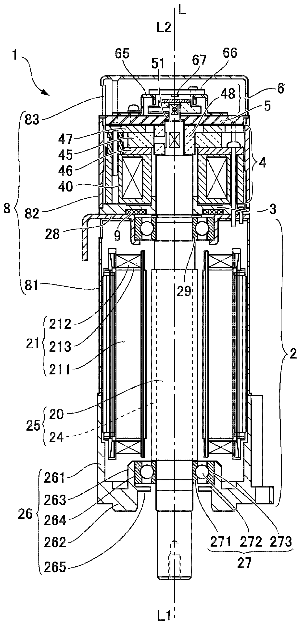
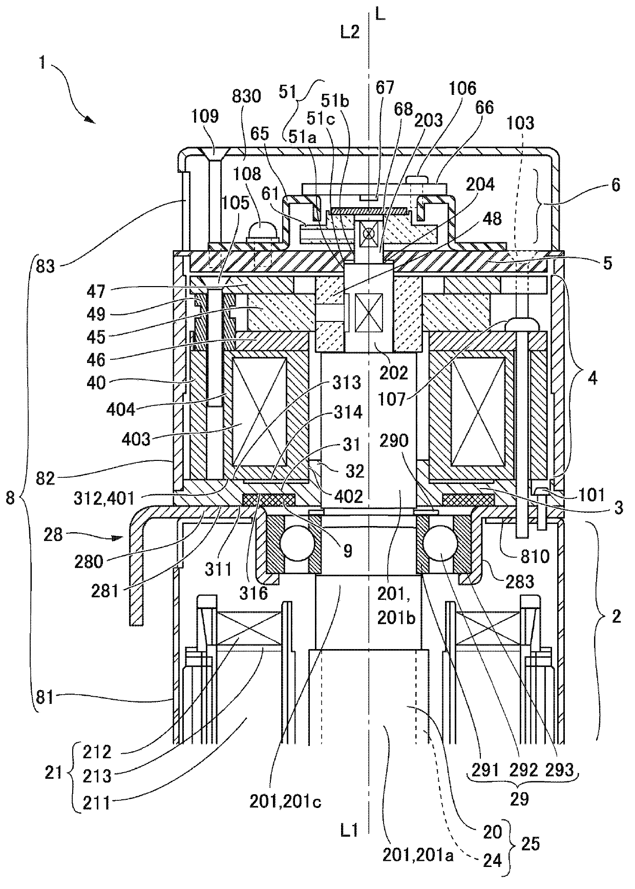
[0049] Hereinafter, an example of a motor with a brake using the present invention will be described with reference to the drawings. In the following description, when indicating the direction of the motor axis L, the side where the motor shaft protrudes is referred to as the output side L1 , and the side opposite to the side where the motor shaft protrudes is referred to as the anti-output side L2 . In addition, in the drawings, the screws 101, 103, and 107 are shown at overlapping positions, but the screws 101, 103, and 107 are arranged at different positions in the circumferential direction.

[0050] (The overall structure of the motor)

[0051] figure 1 is a sectional view of a motor with a brake using the present invention, figure 2 It is an enlarged cross-sectional view showing essential parts of the motor with brake to which the present invention is applied.

[0052] Such as figure 1As shown, in the motor 1 with brake of this example, the motor unit 2 and the brake...


PUM


Abstract

The invention provides a motor with a brake, which can arrange the brake with respect to a motor shaft properly. In the motor (1) with the brake, a brake positioning plate (3) is arranged between the end face of the reverse output side (L2) of a motor part (2) and the end face (401) of the output side of a brake stator (40). The brake positioning plate (3) is provided with a circular end plate part (31) clamped between the end face of the reverse output side (L2) of the motor part (2) and the end face (401) of the output side of the brake stator (40), and a cylinder part (32) vertically protruding from the inner periphery of the circular end plate part (31) toward the reverse output side (L2) to contact with the inner circumferential surface (402) of the brake stator (40). Therefore, the brake positioning plate (3) is positioned by taking the motor part (2) as the reference, and the brake stator (40) is positioned at the motor part (2) by means of the brake positioning plate (3).

Description

technical field [0001] The invention relates to a motor with a brake. Background technique [0002] A motor with a brake has been proposed in which a brake is provided on the opposite output side in the motor axis direction with respect to the motor unit for the purpose of preventing the motor shaft from rotating together with the load when stopped (refer to Patent Document 1). [0003] Here, in the motor with brake described in Patent Document 1, an end plate portion is provided at the end portion on the anti-output side of the bracket surrounding the brake, and the end plate portion is connected to the end surface on the anti-output side of the stator for the brake. Abut. [0004] Patent Document 1: Japanese Patent No. 4457156 [0005] The cylindrical stator for a brake and the motor shaft need to be arranged such that the axial directions of both are parallel to each other so that a load is properly applied to the motor shaft when the brake operates in the motor with br...

Claims


Application Information

Patent Timeline
IPC IPC(8): H02K7/102F16D65/22F16D121/20F16D131/00
Inventor 草间健司谷口幸一中山裕次
Owner NIDEC SANKYO CORP
Why Eureka
Try Eureka