
Lens structure and camera device

A camera device and lens technology, applied in installation, optics, instruments, etc., can solve the problems of reduced resolution, complex lens structure, looseness of the second lens and the third lens, etc., and achieve the effect of reducing the amount of error

Inactive Publication Date: 2013-10-30
ALTEK CORP
View PDF5 Cites 1 Cited by
  • Summary
  • Abstract
  • Description
  • Claims
  • Application Information

AI Technical Summary

Problems solved by technology

Therefore, when the side of the first lens and the inner wall of the lens barrel are worn and the first lens becomes loose, it will also cause the second lens and the third lens to loosen, resulting in inaccurate centering of each lens, and further resulting in a decrease in resolution The problem
[0007] In addition, since the above-mentioned lens groups are formed in a stacked manner, the lens structure is quite complicated.
Therefore, in the manufacture of lenses, only plastic materials can be used as materials, and glass materials cannot be used
If the lens material is made of glass, there will be a problem that the centering position of each lens cannot be consistent

Method used


Image

  • Lens structure and camera device
  • Lens structure and camera device
  • Lens structure and camera device

Examples


Embodiment Construction

[0061] Embodiments of the lens structure and the imaging device thereof according to the present invention will be described below with reference to the relevant drawings. For ease of understanding, the same components in the following embodiments are described with the same symbols.

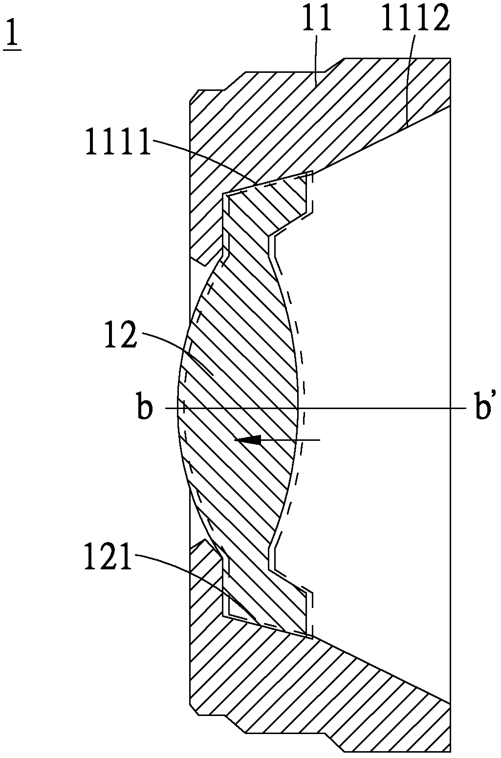
[0062] see Figure 1 to Figure 3 , which are the first schematic diagram to the third schematic diagram of the first embodiment of the lens structure of the present invention. As shown in the figure, the lens structure 1 includes a lens barrel 11 and a lens 12 . The lens barrel 11 is a cylindrical structure, and the lens barrel 11 has an inner wall 111 that is not parallel to the central axis aa'. As for the lens 12, the side between its two surfaces relative to the optical axis bb' corresponds to the inner wall 111 to form a joint edge 121.

[0063] Wherein, when the inner wall 111 is separated from the joint edge 121 by abrasion, the lens 12 is displaced on the optical axis bb', so that the ...


PUM


Abstract

The invention provides a lens structure, including a lens cone which is of a tubular structure and possesses inner sidewalls unparallel with a center shaft; and a lens, wherein a side relative to an optical axis between two sides corresponds with the inner sidewall to form a joint side, and the lens is buckled to the inner sidewall through the joint side so as to be buckled in the lens cone. The beneficial effects are that the lens structure can substantially reduce error amount generated in assembling and avoid lens looseness and inaccurate centering when lens inner sidewalls are worn; meanwhile, inaccurate centering in assembling can be avoided when the lens is prepared by glass materials; inner sidewalls in a lens cone and lens sides can be prevent from squeezing in a process of assembling and clamping the lens cone and the lens; inaccurate centering of each lens in a whole lens group can be avoided when a lens looses.

Description

technical field [0001] The present invention relates to a lens structure, especially a lens structure and an imaging device that can avoid problems such as assembly errors and resolution degradation caused by equipment aging. Background technique [0002] With the development of optical imaging technology, lens modules are widely used in various imaging devices such as digital cameras, video cameras, and mobile phones. Portable electronic devices such as mobile phones integrated with lens modules are favored by many consumers. [0003] Generally, after the lens is assembled into the lens barrel, the lens needs precise positioning. In the prior art, the lens module includes a lens barrel and lenses arranged in the lens barrel. Optical elements such as lenses in the lens barrel are generally fixed in the lens barrel by dispensing glue. [0004] However, if the above-mentioned optical components are not firmly fixed by dispensing glue or the glue is aged, the stability of th...

Claims


Application Information

Patent Timeline
Patent Type & Authority Applications(China)
IPC IPC(8): G02B7/02G03B17/12
Inventor 许宏彬林棋发
Owner ALTEK CORP
Learn More