Eureka AIR delivers breakthrough ideas for toughest innovation challenges, trusted by R&D personnel around the world.

Method for installing distributed sensing optical fibers used for monitoring strain of steel structure

A technology of sensing optical fiber and installation method, which is applied in the direction of using optical devices, measuring devices, instruments, etc., can solve the problems of inconvenient disassembly, uncertain location of steel structure damage and strain, inaccurate strain measurement results, etc., and achieve convenient disassembly process Fast, convenient and fast installation process, accurate measurement results

Inactive Publication Date: 2013-10-30
NINGBO INST OF TECH ZHEJIANG UNIV ZHEJIANG
View PDF5 Cites 5 Cited by
  • Summary
  • Abstract
  • Description
  • Claims
  • Application Information

AI Technical Summary

Problems solved by technology

In the prior art, the sensing optical fiber is fixed by coating the surface of the steel structure with an adhesive, but the deployment method is complex in construction, slow in deployment speed, long in cycle, and inconvenient to disassemble; more importantly, the damage and strain position of the steel structure is not It is determined that this layout method can only monitor the strain of the entire optical fiber layout area, but the specific location of the damage strain cannot be measured; moreover, the process of measuring the strain will be interfered by the temperature difference, and the strain measurement result is inaccurate

Method used


Image

  • Method for installing distributed sensing optical fibers used for monitoring strain of steel structure
  • Method for installing distributed sensing optical fibers used for monitoring strain of steel structure
  • Method for installing distributed sensing optical fibers used for monitoring strain of steel structure

Examples


Embodiment Construction

[0026] The present invention will be further described below in conjunction with the accompanying drawings and specific embodiments.

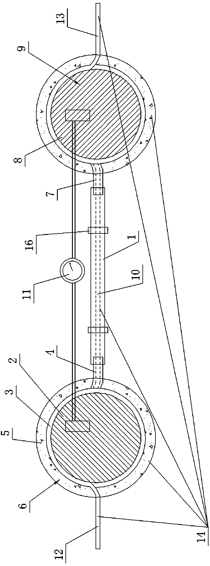
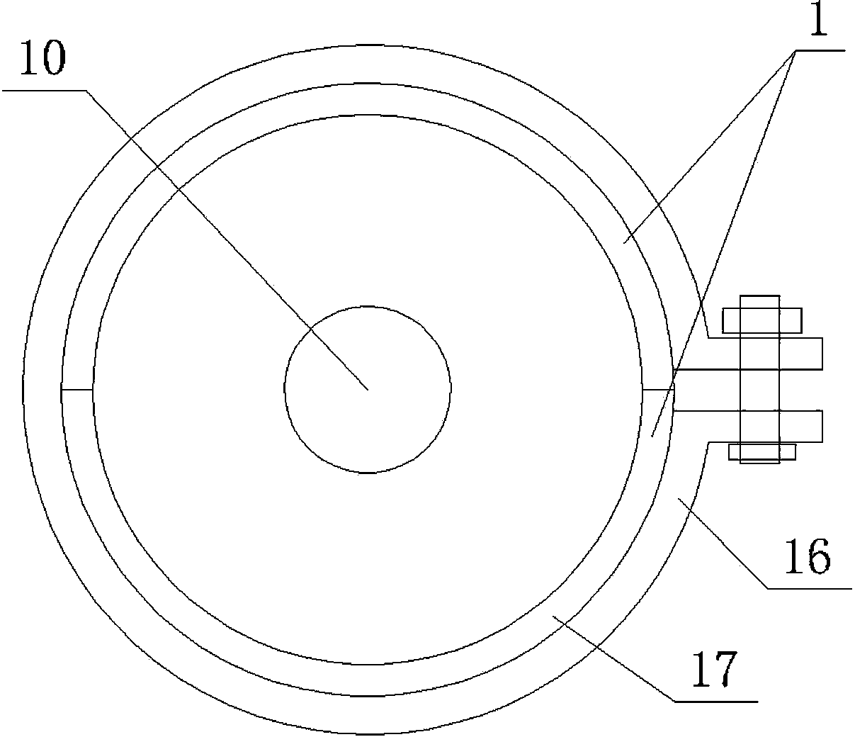
[0027] Such as figure 1 , figure 2 , image 3 , Figure 4 As shown, the present invention is used to install the distributed sensing optical fiber for monitoring the steel structure strain, and its steps are as follows.

[0028] a. Use a sensing fiber to wind multiple turns on the circumferential surface of the first round handle magnet 2 to form a temperature compensation coil 3, and pass the lead-out end of the temperature compensation coil 3 of the sensing fiber through the first correction sleeve 4; wherein, The first round magnet 2 and the second round magnet 8 of subsequent steps are all high-strength magnets with knobs, and the north and south poles of the magnetic block inside the high-strength magnets are rotated by turning the knobs to realize the magnetization process or demagnetization process.

[0029] b. Pouring an epoxy resi...


PUM


Abstract

The invention discloses a method for installing distributed sensing optical fibers used for monitoring strain of a steel structure. The method includes the following steps that a plurality of optical fiber distribution monomers (14) are manufactured, wherein each optical fiber distribution monomer (14) comprises two magnetic bonding ends, a strain monitoring optical fiber section (10), a front section signal transmission optical fiber section (12) and a rear section signal transmission optical fiber section (13); the optical fiber distribution monomers (14) are sequentially connected in series, and optical fiber connectors are welded at the front end of the front section signal transmission optical fiber section (12) of the headmost optical fiber distribution monomer (14) and the rear end of the rear section signal transmission optical fiber section (13) of the backmost optical fiber distribution monomer (14) respectively; then the optical fiber distribution monomers (14) which are connected in series are fixed on the steel structure to be monitored, and then the two optical fiber connectors of the optical fiber distribution monomers (14) which are connected in series are connected to a test instrument. The method for installing the distributed sensing optical fibers is rapid, comprehensive and accurate.

Description

technical field [0001] The invention relates to the field of civil engineering health monitoring, in particular to an installation method of a distributed sensing optical fiber used for monitoring steel structure strain. Background technique [0002] During the service period of steel structures in civil engineering, such as bridges, pedestrian bridges, rails, oil pipelines, etc., due to unfavorable factors such as environmental loads and material performance degradation, a series of damages such as bearing capacity decline and deformation exceeding the limit will inevitably occur. Therefore, it is necessary to carry out strain monitoring for steel structures in civil engineering. [0003] The steel structure in civil engineering has the characteristics of uncertain damage and strain location, and at the same time, the environmental conditions are complex. Therefore, the existing methods of monitoring the strain of steel structures, such as using electrical resistance strain...

Claims


Application Information

Patent Timeline
IPC IPC(8): G01B11/16
Inventor 毛江鸿金伟良崔磊方鹏飞王韬
Owner NINGBO INST OF TECH ZHEJIANG UNIV ZHEJIANG
Why Eureka
Eureka Blog
Learn More