Pneumatic tire

一种充气轮胎、轮胎的技术,应用在充气轮胎的增强层、重型轮胎、轮胎零部件等方向,能够解决偏磨损等问题

Inactive Publication Date: 2013-10-23
BRIDGESTONE CORP
View PDF7 Cites 16 Cited by
  • Summary
  • Abstract
  • Description
  • Claims
  • Application Information

AI Technical Summary

Problems solved by technology

[0006] Also, in the case where a pneumatic tire is mounted to a steering shaft, the tire is likely to be subjected to a side force (SF) at the shoulder end side of the tread caused by a slip angle (slip angle) applied to the tire Partial wear

Method used


Image

  • Pneumatic tire
  • Pneumatic tire
  • Pneumatic tire

Examples


Embodiment

[0072] Tires for trucks and buses with a size of 355 / 50R22.5 were respectively assembled to rims with a size of 11.75×22.5 and filled with an air pressure (internal pressure) of 900 kPa, and in Conventional Example, Comparative Example 1, Comparative Example 2 And in Examples 1 to 8, the tires were subjected to an durability test and an abrasion test under a standard load of about 39 kN at a drum speed of 65 km / h.

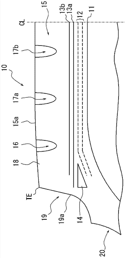
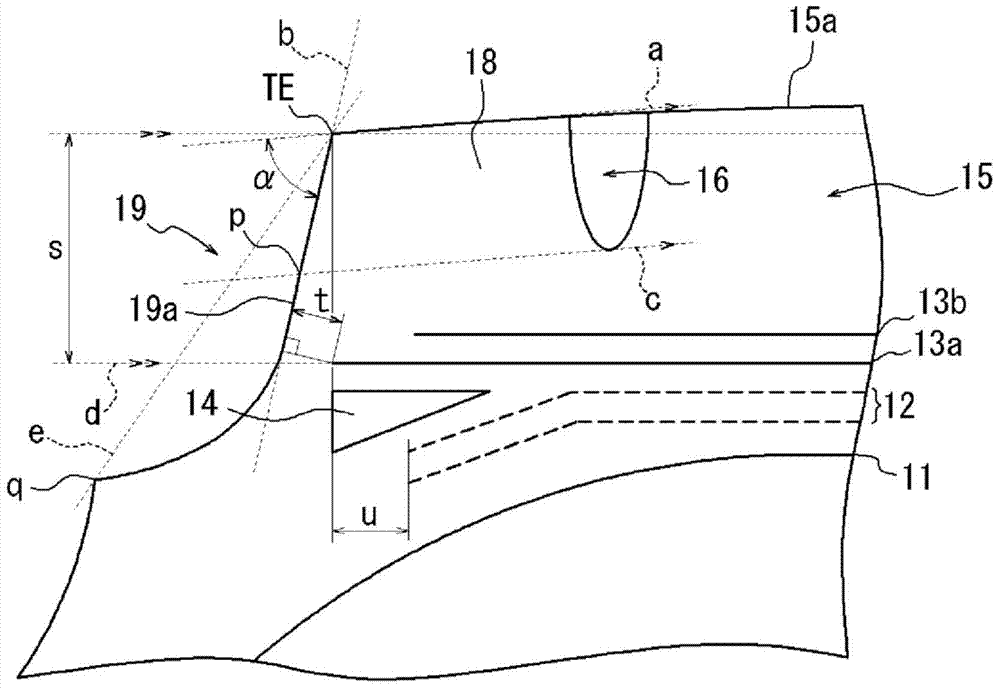
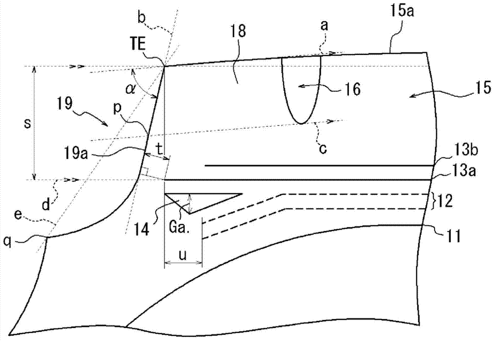
[0073] Here, the Conventional Example and Comparative Examples 1 and 2 each have a shoulder reinforcement portion defined by a straight line connecting the tread end TE and the boundary q and the sidewall portion 20 (instead of a concave shape), while Examples 1 to 8 each have a The shoulder reinforcement portion has a concave shape, that is, a concave shape that connects the tread end TE and the boundary q and the sidewall portion 20 to each other with a concave curve.

[0074] In durability testing, the driving distance is measured before tread separation failure...


PUM


Abstract

A pneumatic tire configured in such a manner that the outer ends of a belt reinforcement layer (12) are located on the outer sides of the outermost grooves (16) in the width direction of the tire, the outermost grooves (16) extending in the circumferential direction of the tire. Buttress portions (19) located on the outer sides of the tread (15) in the width direction of the tire and connecting the surface (15a) of the tread (15) to the sidewalls (20) have outer surfaces which are, in a cross-section of the tire taken in the width direction thereof, recessed so as not to protrude further inward in the width direction of the tire than the outer ends of the surface (15a) of the tread (15) in the width direction of the tire.

Description

technical field [0001] The present invention relates to a pneumatic tire, and more particularly, to a pneumatic tire comprising a circumferential belt arranged outside a carcass layer in the tire radial direction and an angled belt, the pneumatic tire being used for vehicles such as trucks and buses of heavy trucks. Background technique [0002] Conventionally known tires are known which include at least one belt reinforcing layer disposed on the outer peripheral side of the crown region of a carcass that may be radially structured by, for example, at an angle of 5° or less with respect to the tread circumferential direction. The cords extending at an angle of , are formed so that the belt reinforcement extends approximately in the tread circumferential direction, so that radial growth of the tire can be suppressed by the belt reinforcement. [0003] One embodiment of the aforementioned tire includes a pneumatic tire provided with: a pair of bead cores; an annular carcass l...

Claims


Application Information

Patent Timeline
Patent Type & Authority Applications(China)
IPC IPC(8): B60C11/01B60C9/18B60C9/22
CPCB60C2200/06B60C11/01B60C9/185B60C9/18B60C9/22B60C9/28B60C2011/013
Inventor 美浓轮秀明
Owner BRIDGESTONE CORP
Why Eureka
Try Eureka