
Card connector

A card connector and card body technology, applied in the direction of connection, contact part, coupling device, etc., can solve the problems of elastic contact piece movement obstacle, elastic contact piece deformation, etc., to achieve thinning and prevent the generation of chipping dust. Effect

Active Publication Date: 2013-10-23
SMK CO LTD
View PDF8 Cites 14 Cited by
  • Summary
  • Abstract
  • Description
  • Claims
  • Application Information

AI Technical Summary

Problems solved by technology

[0017] In addition, in the above-mentioned conventional technology, when the card body is inserted, the elastic contact piece is pressed by the card body and elastically deformed, and the movable end part acquires a reaction force at the bottom of the insertion groove and slides accordingly. The possibility that the bottom of the insertion groove made of synthetic resin is scratched by the edge portion of the sliding movable piece, and the movable end is caught in the cut portion of the bottom of the insertion groove, thereby elastically contacting the predetermined position of the piece. There is an obstacle to movement, and there is concern about the deformation of the elastic contact piece accompanying this

Method used


Image

  • Card connector
  • Card connector
  • Card connector

Examples


Embodiment Construction

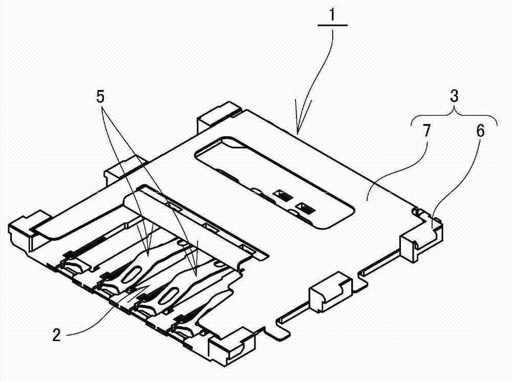
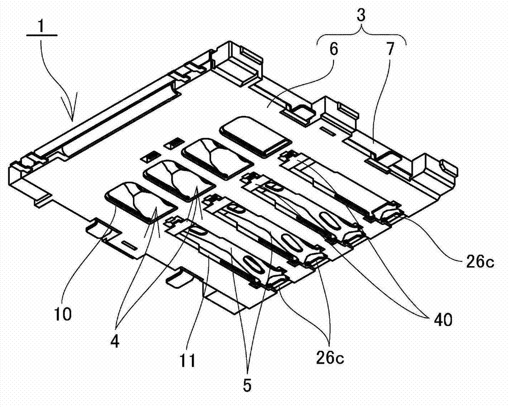
[0057] Next, based on Figure 1 to Figure 11 The shown example describes the first embodiment of the card connector of the present invention. In addition, reference numeral 1 in the figure is a card connector, and reference numeral A is a card body such as an IC card.

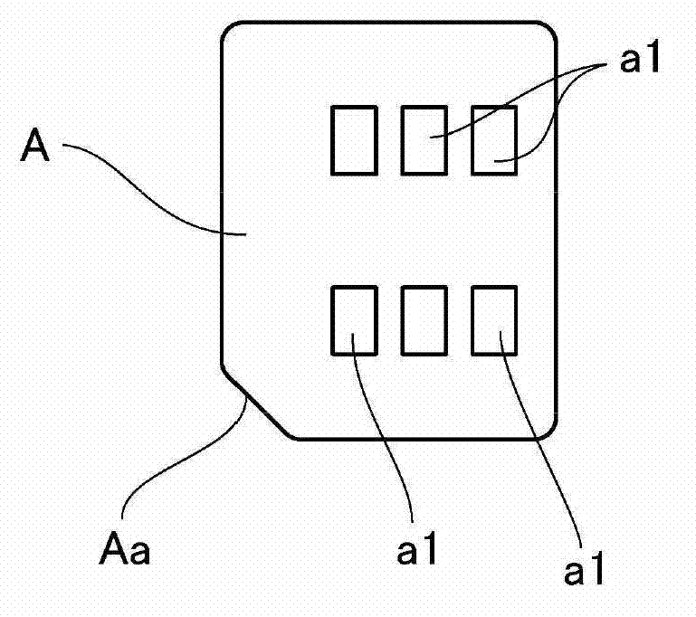
[0058] For example image 3 As shown, the card body A is an IC card, and is formed in a rectangle whose overall length is longer than the overall width of the card, and a positioning portion Aa of a shape cut off in an oblique direction is formed at one corner of the rectangle.

[0059] On one side of the card body A, a pair of signal terminal rows are arranged side by side at intervals in the overall length direction of the card. The pair of signal terminal rows are formed by arranging a plurality of signal terminals a1, a1 ... in the card width direction. .

[0060] The card connector 1 is equipped with: a housing 3 formed with a card body insertion portion 2 for the card body A to be inserted; The body A...


PUM


Abstract

The present invention provides a card connector. The card connector can realize low height and enables a contact to act stably when a card body is inserted into a casing. The contact (5) comprise: a fixed sheet part (20) which is fixed to a bottom plate part (8) formed by insulated synthetic resin through insert molding way; an elastic contact plate part (21) of which one end is used as a fixed end (29) and the other end is used as a movable end (33), wherein a contact point part (31) is formed between the fixed end and the movable end of the elastic contact plate part, the bottom plate part has a metallic slide contact component (12), the slide contact component is exposed at an inner bottom side of a card body inserting part (2), and integrally has a slide contact surface part (40) arranged under the movable end, when the card body (A) is inserted into the card body inserting part, an elastic contact plate is pressed by the card body to perform elastic deformation, the movable end is in sliding contact with the slide contact surface part, two ends of the elastic contact plate are supported at the bottom plate part.

Description

technical field [0001] The present invention relates to a card connector for connecting a card body such as an IC card or a flash memory card to a printed wiring board mounted on electronic equipment such as a mobile phone or a smart phone. Background technique [0002] Conventionally, card bodies such as IC cards and flash memory cards have been used as external storage media for electronic devices such as mobile phones and smartphones, and the card bodies and printed wiring boards mounted on the electronic devices are electrically connected via card connectors. [0003] This type of card connector includes: a housing having a card body insertion portion into which a card body such as an IC card is inserted; and a plurality of contacts having elastic contact pieces protruding from the bottom of the card body insertion portion and being made of a conductive metal plate. , by inserting the card body into the card body insertion part, the signal transmission terminals (solderi...

Claims


Application Information

Patent Timeline
Patent Type & Authority Applications(China)
IPC IPC(8): H01R12/71H01R13/02H01R13/24
Inventor 佐佐木良江尻孝一郎石川达也
Owner SMK CO LTD
Learn More