Eureka AIR delivers breakthrough ideas for toughest innovation challenges, trusted by R&D personnel around the world.

Method for testing node temperature rise of switch tube in switch power source

A test method and technology of switching power supply, which are applied in power supply test, thermometers and thermometers using electrical/magnetic components directly sensitive to heat, etc. problem, to achieve the effect of accurate test data

Active Publication Date: 2013-10-23
BEIJING DYNAMIC POWER CO LTD
View PDF7 Cites 5 Cited by
  • Summary
  • Abstract
  • Description
  • Claims
  • Application Information

AI Technical Summary

Problems solved by technology

But the obvious disadvantage is that the measured value of the junction temperature is an estimated value, which is smaller than the real value, and the error value varies according to different circuits, which is difficult to use as a standard, and the measurement method is not without scientific basis, so that the existing test The measurement error of the method is large, and it is not conducive to the reliability analysis of the product

Method used


Image

  • Method for testing node temperature rise of switch tube in switch power source

Examples


Embodiment Construction

[0012] A method for testing the junction temperature rise of a switching tube in a switching power supply provided by an embodiment of the present invention will be described in detail below with reference to the accompanying drawings.

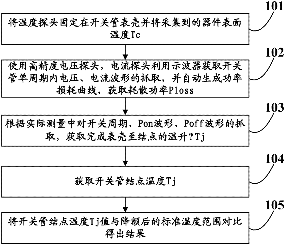
[0013] Such as figure 1 As shown, the flow chart of the test method for the junction temperature rise of the switch tube in a switching power supply provided by the embodiment of the present invention; the measuring equipment used in the test method includes: temperature probe (thermocouple), temperature sampler, digital fluorescent Oscilloscope (high-precision voltage probe: more than 0.1% accuracy, current probe: more than 1% accuracy), computer (directly connected through serial port, optional). Ambient temperature for carrying out the test: the maximum working temperature of the product defined in the design specifications. Test the input and output conditions of the whole machine: input upper and lower limits / rated full load.

[0014] 1...


PUM


Abstract

The invention discloses a method for testing node temperature rise of a switch tube in a switch power source and relates to the electric power electronic test technology field. The method for testing node temperature rise of a switch tube in a switch power source comprises the steps of fixing a temperature probe on a switch tube surface shell and collecting device surface temperature Tc; capturing voltage and current waveforms of the switch tube within a single period by using high-precision voltage and current probes through a oscilloscope, automatically generating a power consumption curve, and obtaining dissipation power Ploss; obtaining and completing temperature rise [delta]Tj from the surface shell to a node according to capture of a switching period, a Pon waveform and a Poff waveform in an actual measurement process; obtaining switch tube node temperature Tj; obtaining a result by comparing the switch tube node temperature Tj with a derated standard temperature scope. The method for testing node temperature rise of a switch tube in a switch power source is characterized in that precise, full and accurate properties of test data are realized; authoritativeness of the test data is fulfilled; the method can help determining a test result of a prototype test phase, and the method can help with roduct reliability analysis.

Description

technical field [0001] The invention relates to the technical field of power electronics, in particular to a method for testing the junction temperature rise of a switching tube in a switching power supply. Background technique [0002] The temperature rise test of the key components in the switching power supply is part of the CMTBF test, and the accuracy of the temperature rise data affects the reliability of the switching power supply product design. As the switch tube of the power device in the main circuit, it is mainly used in PFC circuit and power conversion circuit. The types of switch tube mainly include MOSFET (insulated gate field effect transistor) and BJT (bipolar junction transistor). basically the same as the form. How to judge whether the switch tube device satisfies the actual electrical environment and thermal environment of the applied circuit is an important item in the power supply hardware test. [0003] The operating range of the switching tube junct...

Claims


Application Information

Patent Timeline
IPC IPC(8): G01R31/40G01R19/00G01K7/16
Inventor 李源
Owner BEIJING DYNAMIC POWER CO LTD
Why Eureka
Eureka Blog
Learn More