
Driving force transmission apparatus, and four-wheel-drive vehicle including the driving force transmission apparatus

A transmission device and driving force technology, applied in transmission devices, gear transmission devices, control devices, etc., can solve problems such as inability to ensure cam action

Inactive Publication Date: 2013-10-23
JTEKT CORP
View PDF1 Cites 6 Cited by
  • Summary
  • Abstract
  • Description
  • Claims
  • Application Information

AI Technical Summary

Problems solved by technology

However, in this case, the retainer is usually not limited in rotation, so the cam follower does not follow the cam surface, and the desired cam action cannot be ensured

Method used


Image

  • Driving force transmission apparatus, and four-wheel-drive vehicle including the driving force transmission apparatus
  • Driving force transmission apparatus, and four-wheel-drive vehicle including the driving force transmission apparatus
  • Driving force transmission apparatus, and four-wheel-drive vehicle including the driving force transmission apparatus

Examples


Embodiment Construction

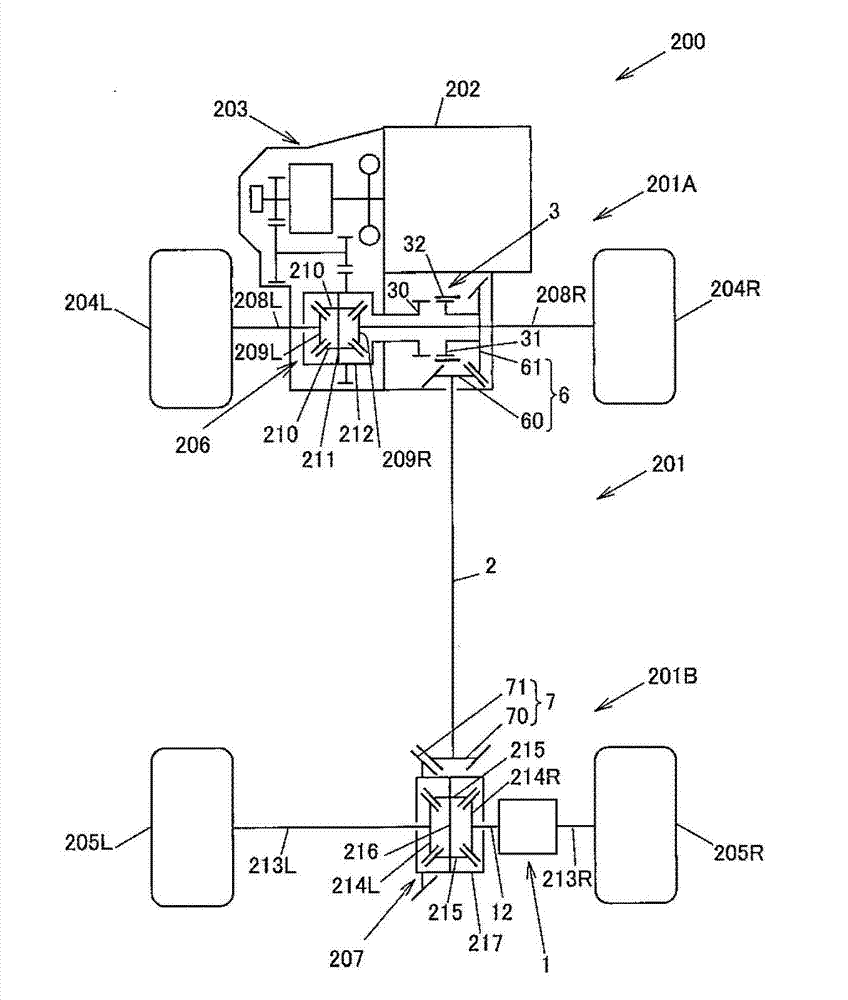
[0024] figure 1 Indicates the outline of a four-wheel drive vehicle. Such as figure 1 As shown, the four-wheel drive vehicle 200 includes a driving force transmission system 201 , an engine (main drive source) 202 , a transmission 203 , front wheels 204L and 204R as main drive wheels, and rear wheels 205L and 205R as auxiliary drive wheels.

[0025] The driving force transmission system 201 is arranged on the driving force transmission path from the transmission 203 side to the rear wheels 205L, 205R side of the four-wheel drive vehicle 200 together with the front differential 206 and the rear differential 207, and the driving force transmission system 201 is mounted on the body (not shown) of the four-wheel drive vehicle 200 .

[0026] The driving force transmission system 201 has a driving force transmission system 201A on the main drive wheel side, a driving force transmission system 201B on the auxiliary driving wheel side, and a driving force transmission shaft (propell...


PUM


Abstract

A driving force transmission apparatus includes a cam mechanism that converts motor torque from an electric motor into first cam thrust force and second cam thrust force. The cam mechanism includes: a cam member that rotates upon reception of the motor torque from an electric motor; a rolling member that rolls on the cam member; and a retainer that outputs the first cam thrust force and the second cam thrust force toward a multiple disk clutch as the rolling member rolls. The rotation of the retainer around a rotation axis is restricted, and the retainer moves in a direction of the rotation axis while retaining the rolling member such that the rolling member is rollable.

Description

technical field [0001] The present invention relates to a driving force transmission device for transmitting driving force from an input shaft to an output shaft, and a four-wheel drive vehicle including the driving force transmission device. Background technique [0002] As a conventional driving force transmission device, there is, for example, a device that is mounted on a four-wheel drive vehicle and couples a pair of rotating members with a clutch so that torque can be transmitted (for example, refer to JP-A-2007-78134). [0003] This driving force transmission device is configured to include a first rotating member (rear wheel output shaft), a second rotating member (clutch drum), a clutch, and a cam mechanism. The above-mentioned first rotating member rotates together with the input shaft. The second rotating member is relatively rotatable on its axis with respect to the first rotating member. The clutch connects the second rotating member and the first rotating mem...

Claims


Application Information

Patent Timeline
Patent Type & Authority Applications(China)
IPC IPC(8): B60K17/346
CPCF16D13/52F16D2023/123F16H1/32F16D23/12F16D28/00B60K17/35
Inventor 藤井则行北村克史铃木邦彦高井智义
Owner JTEKT CORP
Learn More