
Transfer method and transfer apparatus

A technology of transfer printing and transfer printing, applied in the direction of transfer printing, rotary printing machine, duplication/marking method, etc., which can solve the problems that have not been raised

Active Publication Date: 2013-10-23
DAINIPPON SCREEN MTG CO LTD
View PDF6 Cites 5 Cited by
  • Summary
  • Abstract
  • Description
  • Claims
  • Application Information

AI Technical Summary

Problems solved by technology

However, no technique for solving such problems has been proposed so far

Method used


Image

  • Transfer method and transfer apparatus
  • Transfer method and transfer apparatus
  • Transfer method and transfer apparatus

Examples


Embodiment Construction

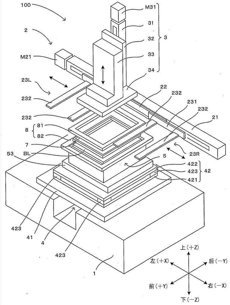
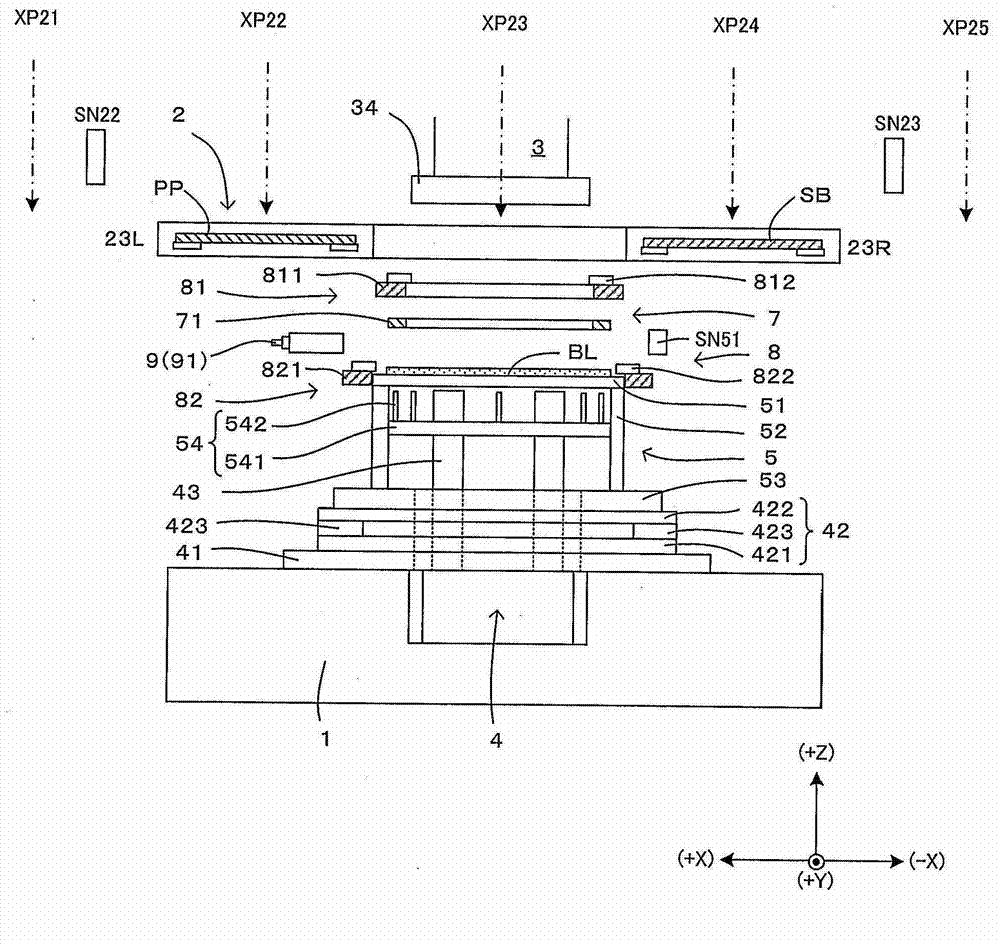
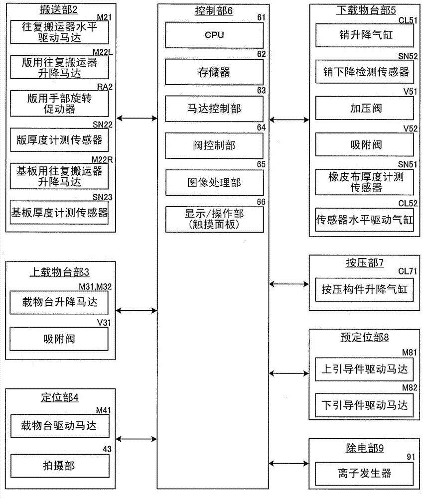
[0050] figure 1 It is a schematic perspective view showing a printing device equipped with the transfer device of the present invention, and shows a state where the device casing is removed in order to clearly show the internal structure of the device. in addition, figure 2 is schematically shown figure 1 A cross-sectional view of the printing apparatus is shown. and, image 3 is shown figure 1 A block diagram of the electrical structure of the device. In this printing apparatus 100, the upper surface of the blanket carried into the apparatus from the front side of the apparatus is brought into close contact with the lower surface of the plate PP carried into the apparatus from the left side of the apparatus, and then peeled off. This uses the pattern formed on the lower surface of the plate PP to write a pattern on the coating layer of the blanket to form a pattern layer (pattern writing process). In addition, in the printing apparatus 100, the upper surface of the bla...


PUM


Abstract

The invention is aimed at providing a positioning processing technique capable of preventing a position mark transferred to a substrate with a transferred object from being hindered in a technique of transferring a transferred object carried by carrier body. A first positioning mark (AM1) formed on a substrate side in advance comprises multiple graph patterns (AP11 to AP14) configured mutually separately and a positioning mark transferring area (TR) is formed and surrounded by the multiple graph patterns (AP11 to AP14). On the rubber blanket of a carrier pattern, a second positioning mark (AM21) formed by pattern forming material is shot as well as the first positioning mark (AM1). The substrate and the rubber blanket are positioned based on the position detecting result of the second positioning mark (AM21) and the first positioning mark (AM1). Then, the second positioning mark (AM21) is positioned at the positioning mark transferring area (TR) and is positioned at a separating position of the graph patterns (AP11 to AP14) and the transferred second positioning mark (AM21) so as to be transferred to the substrate.

Description

technical field [0001] The present invention relates to a transfer method and a transfer device for transferring a pattern or a thin film carried on the surface of a carrier onto a substrate. In particular, it relates to a technique for aligning a substrate and a carrier based on imaging results of alignment marks placed on a carrier. Background technique [0002] As a technique for forming a pattern or a thin film on the surface of a substrate, for example, there is a technique of temporarily supporting a pattern or a thin film as an object to be transferred on the surface of a flat support (such as a glass plate), and by making the support A technique in which the carrier adheres closely to the surface of the substrate to transfer the material to be transferred onto the surface of the substrate. In such a transfer technique, in order to properly transfer an object to be transferred to a predetermined position on the surface of the substrate, positioning processing for ali...

Claims


Application Information

Patent Timeline
Patent Type & Authority Applications(China)
IPC IPC(8): B41M5/382B41F16/00
CPCB41F16/00B41M3/12B41M5/025B41M5/0358
Inventor 谷口和隆川越理史
Owner DAINIPPON SCREEN MTG CO LTD
Learn More