Eureka AIR delivers breakthrough ideas for toughest innovation challenges, trusted by R&D personnel around the world.

Fixed angle constant pressure automatic compensation feeding device and compensation feeding method

An automatic compensation and feeding device technology, applied in the direction of grinding drive device, grinding machine tool parts, metal processing equipment, etc., can solve the problem that the control accuracy of blade size cannot reach high-precision grinding blade belt, and cannot be scaled and batched Production of high-precision sharp knife belts, high-precision grinding of difficult knife belts, etc., to achieve the effect of simple high-precision grinding, improved surface roughness level, and improved sharpness

Active Publication Date: 2015-08-19
SHANGHAI XINPENG PRINTING EQUIP
View PDF5 Cites 0 Cited by
  • Summary
  • Abstract
  • Description
  • Claims
  • Application Information

AI Technical Summary

Problems solved by technology

There are many variables between the amount of wear of the grinding wheel and the running speed of the blade and the physical and chemical properties of the blade when grinding and sharpening. Can not meet the requirements of high-precision grinding knife belt
[0006] Because of the grinding process of the blade edge, the grinding wheel wears continuously and non-linearly. Even the feeding method with an automatic control system cannot fully realize the high-precision grinding and cutting of the blade. The delivery method (method) is complex in structure, large in investment, and cost-effective
Practice has proved that the existing grinding wheel feeding methods and methods are very difficult to achieve high-precision grinding of knife belts. This has been plagued by knife belt manufacturers in my country. Technical difficulties in producing qualified high-precision sharp knife belts

Method used


Image

  • Fixed angle constant pressure automatic compensation feeding device and compensation feeding method
  • Fixed angle constant pressure automatic compensation feeding device and compensation feeding method
  • Fixed angle constant pressure automatic compensation feeding device and compensation feeding method

Examples


Embodiment Construction

[0035] According to the claims of the present invention and the contents disclosed in the summary of the invention, the technical solution of the present invention is specifically described as follows.

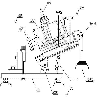
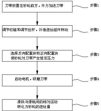
[0036] Please see attached figure 1 and attached figure 2 As shown, the fixed angle constant pressure automatic compensation feed device of the present invention includes: a base plate 01, a grinding assembly 02, an angle adjustment assembly 03 and a compensation feed assembly 04; the grinding assembly 02 is arranged above the base plate 01 through the angle adjustment assembly 03, and the grinding assembly 02 rotates in a vertical plane above the bottom plate 01; the compensating feed assembly 04 is arranged on the grinding assembly 02.

[0037] The grinding assembly 02 includes a grinding wheel 021 and a motor 022. The grinding wheel 021 is arranged on the shaft head of the motor 022 and rotates synchronously with the shaft head of the motor 022. The front end of the grind...


PUM


Abstract

A constant angle constant pressure automatic compensation feeding device comprises a base plate, a grinding assembly, an angle adjusting assembly and a compensation feeding assembly. The compensation feeding assembly solves the problem that a grinding wheel is difficult to feed automatically and accurately in a traditional method for grinding a cutter belt edge. The compensation feeding assembly is good in operability, simple in angle adjustment and capable of meeting the process technical requirement for producing a high-accuracy cutter belt, enables high-accuracy grinding of the cutter belt edge to be simple and controllable and is easy to popularize and apply. In the service life duration of the grinding wheel, manual intervention or intervention in other modes are not required. By means of a compensation feeding method for the constant angle constant pressure automatic compensation feeding device, the sharpness of the cutter belt edge is greatly improved, a perfect cutter belt edge shape is achieved, the surface roughness grade of the edge is greatly improved, and the mirror face grade requirement can be met.

Description

technical field [0001] The invention relates to a grinding device for a knife belt, in particular to a constant-angle constant-pressure automatic compensation feeding device and a compensation feeding method thereof. Background technique [0002] When the grinding method is used to process the cutting edge of the knife belt, the grinding wheel is in a continuous and non-linear wear process, and it is necessary to continuously feed the grinding wheel relative to the processing part of the knife belt to compensate for the wear of the grinding wheel. When the existing grinding method processes the cutting edge of the knife belt, the feeding mode of the grinding wheel is as follows: [0003] 1. Manual screw rod to adjust the feed. The feed rate of the grinding wheel in this method is judged by the experience of skilled workers, and the product quality is not stable, especially the accuracy of the blade height cannot be accurately controlled. [0004] 2. Feed by pneumatic press...

Claims


Application Information

Patent Timeline
Patent Type & Authority Patents(China)
IPC IPC(8): B24B47/25
Inventor 蒋鹏海
Owner SHANGHAI XINPENG PRINTING EQUIP
Why Eureka
Eureka Blog
Learn More