Observation and test apparatus for cavity evolution in test pieces under tensile impact and test method

A test method and cavity technology, which is applied in the direction of testing the strength of materials with a single impact force to achieve the effect of a simple test method

Inactive Publication Date: 2015-06-17
NINGBO UNIV
View PDF5 Cites 2 Cited by
  • Summary
  • Abstract
  • Description
  • Claims
  • Application Information

AI Technical Summary

Problems solved by technology

However, there is currently no experimental device and test method for observing the evolution of holes in slab members under impact tension.

Method used


Image

  • Observation and test apparatus for cavity evolution in test pieces under tensile impact and test method
  • Observation and test apparatus for cavity evolution in test pieces under tensile impact and test method
  • Observation and test apparatus for cavity evolution in test pieces under tensile impact and test method

Examples


Embodiment Construction

[0022] The present invention will be further described in detail below in conjunction with the accompanying drawings and embodiments.

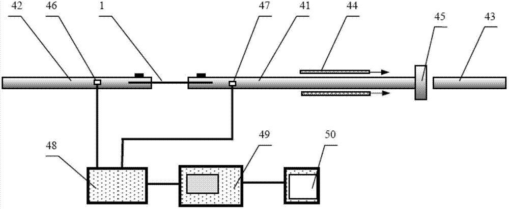
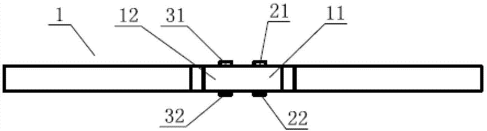
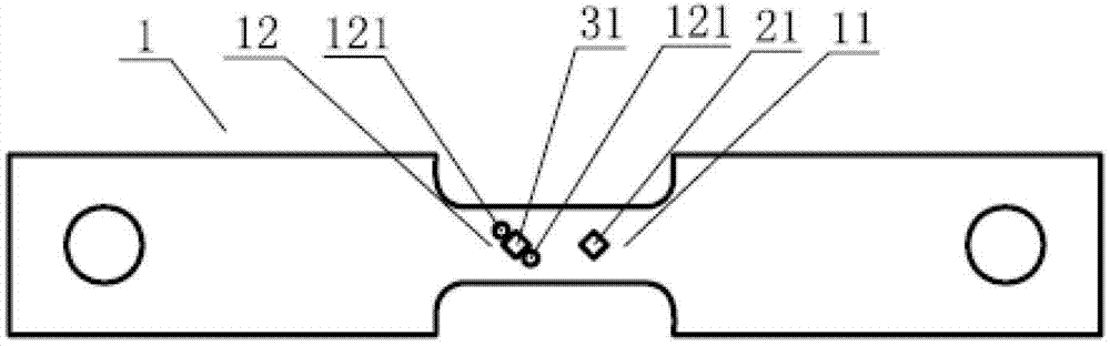
[0023] As shown in the figure, a test device for observing the evolution of voids in a test piece under impact tension includes micro-strain gauges symmetrically arranged on the two surfaces of the strip test piece 1, and the micro-strain gauges include two first micro-strain gauges 21 and 22 and two second micro-strain gauges 31 and 32, the strip test piece 1 includes a non-cavity cluster region 11 and a hole cluster region 12 preset with a plurality of holes 121, and the strip test piece 1 is fixedly installed on Between the input rod 41 and the output rod 42 of the Hopkinson rod device, the non-cavity cluster area 11 is close to the input rod 41, the cavity cluster area 12 is close to the output rod 42, and the two first micro-strain gauges 21 and 22 are arranged on the non-cavity cluster area 12. In the hole cluster area 11, two second mic...


PUM


Abstract

The invention discloses an observation and test apparatus for cavity evolution in test pieces under tensile impact and a test method. The observation and test apparatus comprises first micro strain gauges and second strain gauges symmetrically arranged at two surfaces of a lath test piece, wherein the lath test piece comprises a non-cavity cluster region and a cavity cluster region and is fixedly mounted on a Hopkinson rod device, the non-cavity cluster region is near an input rod, the cavity cluster region is near an output rod, a plurality of the first micro strain gauges are arranged at the non-cavity cluster region, a plurality of the second micro strain gauges are arranged between cavities, one first micro strain gauge is connected with a high-speed camera through a super dynamic strain gauge, and the remaining first micro strain gauge and all the second strain gauges are connected with a oscilloscope through the super dynamic strain gauge. According to the invention, researchers can conveniently master an evolution rule of the cavities in the test pieces under controllable and measurable tensile impact load. The apparatus and the method can also be applied for impact tensile strength and failure test of industrial and engineering lath-structural members containing pores.

Description

technical field [0001] The invention relates to an observable test device and a test method for micro-cavity growth and aggregation rules under impact tension, and can also be applied to impact tensile strength and failure tests of lath structural parts containing holes. Background technique [0002] The dynamic tensile fracture of ductile metal materials has been attributed to the dynamic nucleation, growth and aggregation process of micro-cavities inside the material from the perspective of micro- and micro-mechanisms. Among them, the dynamic accumulation of holes induces a mutation, forming a dynamic fracture of the material. Attention to this critical stage of the dynamic fracture process has become the frontier of dynamic fracture research. Although there are several theoretical models about hole aggregation, there are no experimental devices and methods for direct testing and evaluation. The reason is that the micro-cavity is located inside the material, which is dif...

Claims


Application Information

Patent Timeline
Patent Type & Authority Patents(China)
IPC IPC(8): G01N3/30
Inventor 王焕然马东方陈大年
Owner NINGBO UNIV
Why Eureka
Try Eureka