
Magnetron sputtering equipment

A technology of magnetron sputtering and equipment, applied in the field of magnetron sputtering, which can solve the problems of high sputtering power, high total bombardment power, shortening the distance between substrate and target, etc.

Active Publication Date: 2013-10-09
SHENZHEN INST OF ADVANCED TECH +1
View PDF5 Cites 1 Cited by
  • Summary
  • Abstract
  • Description
  • Claims
  • Application Information

AI Technical Summary

Problems solved by technology

Using higher sputtering power and shortening the distance between the substrate and the target will make the charged positive ions from multiple target surfaces obliquely incident on the substrate at the same time, and the total bombardment power that the substrate bears is relatively large. Deposits on the surface of the substrate will cause re-sputtering to leave the sample surface
The surface of the sample will produce obvious composition and structure inhomogeneity, and the resulting large number of defects will also greatly affect the crystal quality of the film

Method used


Image

  • Magnetron sputtering equipment
  • Magnetron sputtering equipment
  • Magnetron sputtering equipment

Examples


Embodiment Construction

[0027] In order to facilitate the understanding of the present invention, the present invention will be described more fully below with reference to the associated drawings. Preferred embodiments of the invention are shown in the accompanying drawings. However, the present invention can be embodied in many different forms and is not limited to the embodiments described herein. On the contrary, the purpose of providing these embodiments is to make the disclosure of the present invention more thorough and comprehensive.

[0028] It should be noted that when an element is referred to as being “fixed” to another element, it can be directly on the other element or there can also be an intervening element. When an element is referred to as being "connected to" another element, it can be directly connected to the other element or intervening elements may also be present. The terms "vertical," "horizontal," "left," "right," and similar expressions are used herein for purposes of ill...


PUM


Abstract

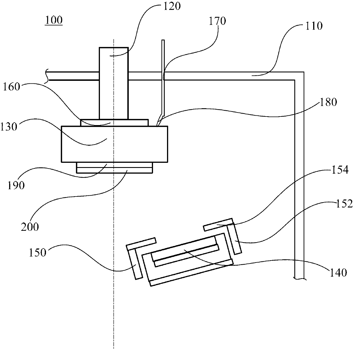
The invention discloses magnetron sputtering equipment. The magnetron sputtering equipment comprises a vacuum chamber wall, a connecting shaft, a workbench and an electric conduction electrode, wherein the vacuum chamber wall surrounds a vacuum chamber; one end of the connecting shaft is connected to the vacuum chamber wall, the workbench is arranged in the vacuum chamber and is arranged on the other end of the connecting shaft, and the workbench is used for fixing a substrate; the electric conduction electrode is arranged on the vacuum chamber wall in a penetrating manner, one end of the electric conduction electrode is connected with the workbench, the workbench is electrically connected with an external power source through the electric conduction electrode, and the external power source applies high potential on the workbench through the electric conduction electrode. The magnetron sputtering equipment provided by the invention has the advantages that the workbench and the substrate are protected by the high potential, electrification positive ions flying to the substrate is influenced by electric field acting force in the opposite direction, the quantity and energy of electrification positive particles are greatly reduced, the bombardment of the surface of the substrate caused by the electrification positive particles is reduced, the sediment deposited on the surface of the substrate is protected, the surface of the sediment is smooth, and the quality of a crystal is good.

Description

technical field [0001] The invention relates to magnetron sputtering technology, in particular to a magnetron sputtering device. Background technique [0002] As a common physical vapor deposition method, magnetron sputtering has been successfully applied to the preparation of different thin films. The magnetron sputtering method uses the characteristic that charged ions have certain kinetic energy after being accelerated in an electric field, and guides the ions to the material to be sputtered (sputtering target) as the target electrode (cathode). When the energy of the ions is suitable, the incident ions collide with the atoms on the surface of the target, and the latter are sputtered out. These sputtered atoms have a certain kinetic energy, and will fly in a certain direction and shoot towards the substrate. and deposited on the substrate to achieve thin film growth. During the sputtering process, the gas pressure and power of the sputtering can be controlled and the di...

Claims


Application Information

Patent Timeline
IPC IPC(8): C23C14/35
Inventor 冯叶杨春雷程冠铭于冰鲍浪郭延璐徐苗苗肖旭东
Owner SHENZHEN INST OF ADVANCED TECH
Learn More