
Tubular furnace and waste lubricating oil recovery device formed thereby

A technology of waste lubricating oil and recovery device, which is applied in the direction of lubricating compositions, etc., which can solve the problems of coking, low oil yield, and blockage of heating pipes, and achieve the effects of high oil yield, large processing capacity, and uniform heating rate

Inactive Publication Date: 2013-10-09
SHANGQIU DONGHE SPECIAL EQUIP CO LTD
View PDF3 Cites 4 Cited by
  • Summary
  • Abstract
  • Description
  • Claims
  • Application Information

AI Technical Summary

Problems solved by technology

[0003] A tube furnace is needed in the process of treatment. However, the existing tube furnace is a vertical tube furnace, and its heating tubes are distributed vertically. The tube length is about several hundred meters. During the heating process, it is easy to cause heating. Tube blockage; In addition, waste engine oil generally contains metal shavings, viscous agents, etc., and it is easy to cause blockage of the heating tube when it passes through a long vertical heating tube during the recycling process.
In addition, in the traditional single-pot production, only one reactor is used to distill waste lubricating oil, the oil yield is low, and coking occurs

Method used


Image

  • Tubular furnace and waste lubricating oil recovery device formed thereby
  • Tubular furnace and waste lubricating oil recovery device formed thereby
  • Tubular furnace and waste lubricating oil recovery device formed thereby

Examples


Embodiment Construction

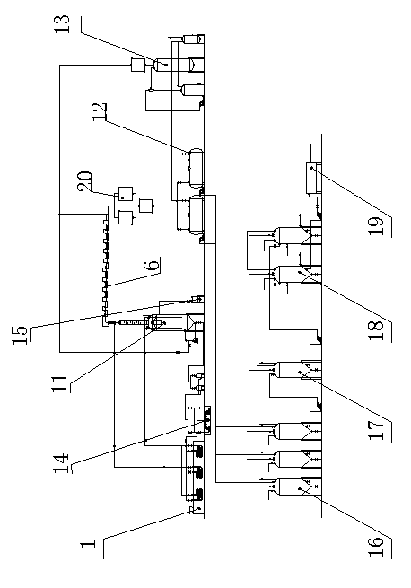
[0012] As shown in the accompanying drawings, the present invention includes a tube furnace 1, waste lubricating oil enters the tube furnace 1 for heating after pretreatment, and the heated oil enters a still 11 and is divided into two parts. Part of the cracked oil enters the oil storage tank 12, and after being filtered by the pickling tank 16, the alkali washing tank 17, the clay tank 18, and the plate and frame filter 19, light fuel oil is obtained, and the other part passes through the residual oil tank 13 for deslagging Finally, heavy fuel oil is obtained, which is characterized in that: the heating tube of the tube furnace 1 is placed horizontally, the tube furnace 1 is connected to the still 11 through the oil pump 14, and the still 11 is connected with an overflow tank 15. The crude oil from the still 11 is sent to the tube furnace through the oil pump 14 for heating. Compared with the traditional single-pot production and vertical tube furnace, this structure has the...


PUM


Abstract

The invention discloses a tubular furnace and a waste lubricating oil recovery device. The tubular furnace comprises a furnace body which comprises a furnace head, a furnace body, a furnace tail, heating pipes and an exhaust device, wherein the heating pipes are transversely arranged in the furnace body in parallel and are connected with a control valve. The waste lubricating oil recovery device comprises the tubular furnace, wherein waste lubricating oil enters into the tubular furnace to be heated, and the heated oil enters into a distillation kettle to be divided into two parts, wherein one part of distilled oil enters into an oil storage tank and is acid-washed and alkali-washed, subjected to impurity removal by a white clay tank and filtered by a plate and frame filter to obtain light fuel oil. The other part is deslagged through a slag oil tank to obtain heavy fuel oil. The heating pipes of the tubular furnace are transversely arranged and the tubular furnace is connected with the distillation kettle through an oil pump. An overflow tank is connected to the distillation kettle. The heating pipes of the tubular furnace are transversely arranged, so that the furnace is not easy to coke. Compared with conventional single kettle production and vertical tubular furnace production, the fuel oil recovery device has the characteristics of anti-coking performance, large handling capacity and high oil yield.

Description

technical field [0001] The invention belongs to the field of recycling waste lubricating oil, in particular to a device for recycling waste lubricating oil. Background technique [0002] Taking waste lubricating oil as an example, there are about 200 million cars in operation in my country at present, and each car changes the oil twice a year, each time for 3 liters, and the amount of waste oil replaced every year is 200 million vehicles × 2 × 3 liters =1.2 billion liters. If these waste materials are recycled, a lot of cost can be saved every year, and environmental pollution can be reduced. Many factories recycle these materials and process them into refined oil for reuse through waste lubricating oil recovery equipment. [0003] A tube furnace is needed in the process of treatment. However, the existing tube furnace is a vertical tube furnace, and its heating tubes are distributed vertically. The tube length is about several hundred meters. During the heating process, it...

Claims


Application Information

Patent Timeline
IPC IPC(8): C10M175/00
Inventor 李栋
Owner SHANGQIU DONGHE SPECIAL EQUIP CO LTD
Learn More