A corrugated foil mold and its manufacturing process

A corrugated foil and mold technology, applied in the field of corrugated foil mold and its manufacturing process, can solve the high requirements of bearing machining accuracy and assembly precision, the rotor system is difficult to meet the reliability and stability, and the corrugated foil manufacturing process is complex and other problems, to achieve the effect of convenient and fast manufacturing process, high structural size and smooth surface

Inactive Publication Date: 2015-08-05
NANJING UNIV OF AERONAUTICS & ASTRONAUTICS
View PDF4 Cites 1 Cited by
  • Summary
  • Abstract
  • Description
  • Claims
  • Application Information

AI Technical Summary

Problems solved by technology

The rotor system supported by rigid bearings is difficult to meet the requirements of reliability and stability, the bearing processing accuracy and assembly accuracy are high, and the problem of short service life has not been resolved
The corrugated foil is a key part of the entire bearing, but the manufacturing process of the corrugated foil is complicated. It takes a lot of work to select the material of the corrugated foil, determine the structural size, forming process, heat treatment, and surface treatment, so the investment in research and development is large.

Method used


Image

  • A corrugated foil mold and its manufacturing process
  • A corrugated foil mold and its manufacturing process
  • A corrugated foil mold and its manufacturing process

Examples


Embodiment Construction

[0030] The technical solution of the present invention will be described in detail below in conjunction with the accompanying drawings.

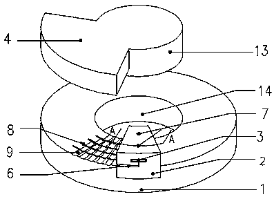
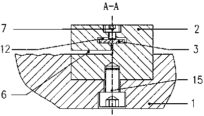
[0031] Please refer to figure 1 and combine Figure 2 to Figure 5 As shown, the corrugated foil mold of the present invention includes four parts: a mold chassis 1 , a positioning block 2 , a spacer 3 and a pressing block 4 . A concave mold corresponding to the corrugated foil sheet 5 is processed on the mold chassis 1. The concave mold here refers to the first annular gap 8 and the groove 9 on the mold chassis 1 described below. Along the two mutually perpendicular gaps 6 in the circumferential direction and the vertical direction, the two M2 socket head cap screws 7 in the screw holes of the positioning block 2 fix the corrugated foil 5 by pressing the gasket 3 in the rectangular groove 12 .

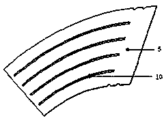
[0032] The first annular gap 8 and the groove 9 on the mold chassis 1 correspond to the distribution of the second annular gap 10 and the foil arc...


PUM


Abstract

A wave foil die comprises a die base, a locating block, a cushion piece and a pressing block, a female die is formed on the die base, and a bent wave foil semi-finished product is arranged in the female die. The wave foil die further comprises a polytetrafluoroethylene sheet placed on the wave foil semi-finished product, a mandril of the pressing block and a center hole of the die base are coaxial, the pressing block is placed on the polytetrafluoroethylene sheet, one side face of the pressing block is attached to one side face of the locating block, the locating block is placed on a working face of the die base, a rectangular groove and a screw hole close to the rectangular groove are formed in the locating block, and the cushion piece is placed in the rectangular groove. The wave foil die further comprises an M4 inner hexagon screw and an M2 inner hexagon screw, wherein the M4 inner hexagon screw is inserted in the back face of the die base to connect the locating block and the die base into a whole, and the M2 inner hexagon screw is arranged in the screw hole and fixes a wave foil by pressing the cushion piece in the rectangular groove tightly. A flexible molding method is adopted in the wave foil, a male die for the wave foil die is not needed, and machining cost of the die is reduced.

Description

technical field [0001] The invention relates to a wave foil mold and a manufacturing process thereof, in particular to a wave foil mold in a separate wave foil dynamic pressure gas thrust bearing and a manufacturing process thereof, belonging to the field of gas dynamic pressure bearings. Background technique [0002] Dynamic pressure gas bearing is a fluid film lubricated bearing with gas as the lubricating medium. Compared with traditional liquid lubricated bearings and rolling bearings, dynamic pressure gas bearing has high speed, low friction, low noise, no pollution, High working precision and high reliability. Its working principle is to form two high-speed relative moving surfaces forming a wedge-shaped gap, and the gas is brought into the wedge-shaped gap under the action of the gas's own viscosity to form a dynamic pressure fluid film that can withstand axial loads. Compared with static pressure gas bearings, The aerodynamic pressure bearing does not require extern...

Claims


Application Information

Patent Timeline
Patent Type & Authority Patents(China)
IPC IPC(8): B21D37/10B23P15/00
Inventor 马希直贺焕源
Owner NANJING UNIV OF AERONAUTICS & ASTRONAUTICS
Why Eureka
Try Eureka