Vacuum bubble switching mechanism and on-load tap-changer

A switching mechanism and on-load tapping technology, which is applied in transformers, electrical components, variable inductors, etc., can solve problems such as longitudinal errors, high structural precision, and difficult installation, so as to improve accuracy, improve motion accuracy, The effect of improving work reliability

Active Publication Date: 2013-10-02
GUANGZHOU DEPOSON ELECTRIC TECH
View PDF8 Cites 2 Cited by
  • Summary
  • Abstract
  • Description
  • Claims
  • Application Information

AI Technical Summary

Problems solved by technology

However, this structure has the following disadvantages: (1) Since there is a gap between the roller bearing and the insulating plate groove, the copy plate constrained in this way can be shifted in the longitudinal direction, and this shift will directly affect the vacuum bubble stroke. (2) When the slide plate is tilted by force, the profiled plate is also tilted, which also causes the position of the profiled plate to change, and also produces an error in the longitudinal direction, which will also be reflected in the vacuum bubble. On the working stroke; (3) This kind of structure requires high precision and is difficult to install

Method used


Image

  • Vacuum bubble switching mechanism and on-load tap-changer
  • Vacuum bubble switching mechanism and on-load tap-changer

Examples


Embodiment 1

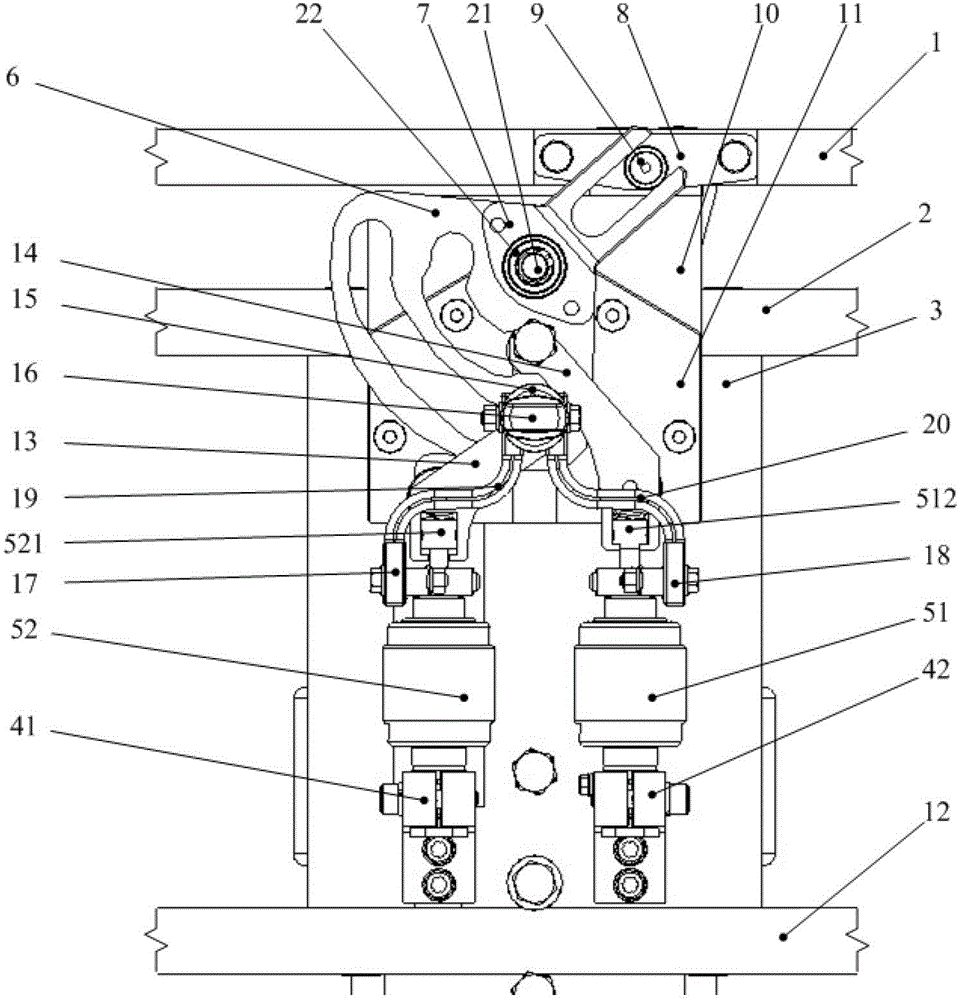
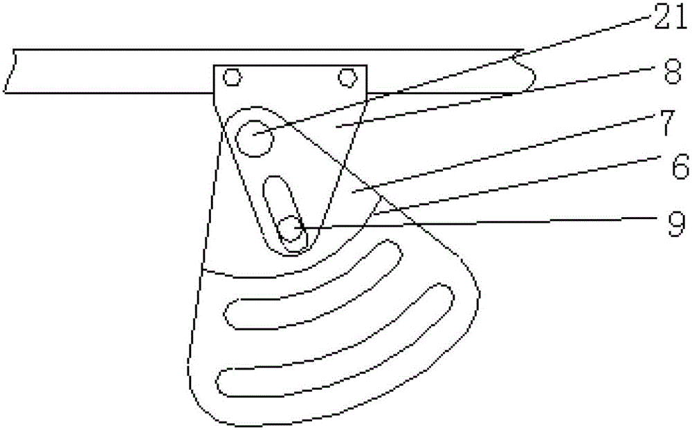
[0021] Such as figure 1 As shown, the vacuum bubble switching mechanism described in this embodiment includes a guide plate, a switching block 8, a shift fork 7, a profiling plate 6 and two vacuum bubble structures, the shift fork 7 is provided with a bearing mounting hole, and a rolling bearing is installed in it. 22. A hole is provided on the guide plate 11, and a bolt 21 is fixed in the hole. The rolling bearing 22 is installed on the bolt 21 together with the shift fork 7, so that the shift fork 7 can rotate around the fixed bolt. The profiling plate 6 is fixed on the shift fork 7 by bolts, and can rotate with the shift fork 7 rotation. Switch shift block 8 is installed on one side of slide plate 1, and a roller bearing 9 is installed on it, places shift fork 7 fork-like grooves, always contacts with fork-like groove one side.

[0022] The working process of this embodiment is: when the slide plate 1 makes a horizontal step movement under the action of the external power ...

Embodiment 2

[0027] Present embodiment except following feature other structures are with embodiment 1:

[0028] In this embodiment, the switching block is fixed on the side of the slide plate, and the shift fork 7 is mounted on the bolt 21 through a rolling bearing, and a long slot is opened on it, in which the roller bearing 9 on the switching block 8 is placed. The profiling plate 6 and the shift fork 7 are welded as one. The working method of this structure is: when the slide plate 1 slides to the left or right, it drives the switching block 8 and the roller bearing 9 to move to the left or right, and at the same time, the shift fork 7 is moved to the left or right by the roller bearing 9 Swing to the right, drive the profiling plate on it to swing around the latch 21.


PUM


Abstract

The invention discloses a vacuum bubble switching mechanism and an on-load tap-changer. The vacuum bubble switching mechanism comprises a guide plate, a switching shifting block, a shifting yoke, a template and two vacuum bubble structures, wherein the switching shifting block is fixed on a sliding plate; the shifting yoke is rotationally connected with the switching shifting block, fixedly connected with the template, and mounted on the guide plate by a bearing; a plurality of arc guide grooves are formed in the template; position lifting devices of the two vacuum bubble structures are arranged in the arc guide grooves, and connected with the tail ends of vacuum bubble moving contacts; the sliding plate makes horizontal step change motion under the action of an external power driving mechanism; the switching shifting block drives the shifting yoke and the template to rotate in a plane; and the two vacuum bubble structures move up and down along the arc guide grooves in the template. The on-load tap-changer adopts the vacuum bubble switching mechanism. According to the vacuum bubble switching mechanism, the template is separated from the sliding plate; slight inclination of the sliding plate cannot influence a working condition of the template and working strokes of vacuum bubbles; and the vacuum bubble switching mechanism has the advantages of low mounting difficulty and high accuracy.

Description

technical field [0001] The invention relates to the field of research on an on-load tap changer for a power transformer, in particular to a vacuum bubble switching mechanism for an on-load tap changer and the on-load tap changer. Background technique [0002] The vacuum bubble used for vacuum on-load tap changer is an extremely important switching element, and its stroke control will have a great impact on the work of the vacuum bubble. Effective and high-precision control of its stroke is to make the vacuum bubble work normally. The essential. [0003] The driving device adopted in the prior art is to fix a square profile plate on the side of the slide plate, that is, the profile plate and the slide plate are fixed as one, and the profile plate constrains its longitudinal direction through a roller bearing fixed on the insulating plate, meaning It restricts the longitudinal movement of the profiling board and plays the role of supporting the sliding board. However, this s...

Claims


Application Information

Patent Timeline
IPC IPC(8): H01H1/56H01F29/04
Inventor 钟建华林广斌张文英
Owner GUANGZHOU DEPOSON ELECTRIC TECH
Why Eureka
Try Eureka