
Method for battery module address assignment of battery energy storage system

A battery module, battery technology, applied in electrical program control, comprehensive factory control, comprehensive factory control and other directions, can solve the problems of large dial switch, increased controller volume and weight, long operation time, etc., to achieve anti-electromagnetic The effect of strong interference ability, low promotion cost and long transmission distance

Active Publication Date: 2013-10-02
HUIZHOU EPOWER ELECTRONICS
View PDF9 Cites 25 Cited by
  • Summary
  • Abstract
  • Description
  • Claims
  • Application Information

AI Technical Summary

Problems solved by technology

This method has the following disadvantages: ①. Manpower is required to toggle the switch, which is prone to errors; ②. Manually toggle the switch, which increases the difficulty of waterproofing the controller; ③. Each slave controller needs to be toggled manually, and the operating time Long, low coding efficiency; ④. The DIP switch is bulky, increasing the volume and weight of the controller
This method has the following disadvantages: ①. It is necessary to manually code the ID of each slave controller. When there are many slave controllers, the operator is easy to get the ID wrong; ②. Professional technicians are required, because manpower is required to operate the handheld device ID coding requires high technical requirements for operators; ③. The operation time is long and the coding efficiency is low; ④. Hand-held development equipment is required, which increases the cost

Method used


Image

  • Method for battery module address assignment of battery energy storage system
  • Method for battery module address assignment of battery energy storage system

Examples


specific Embodiment approach

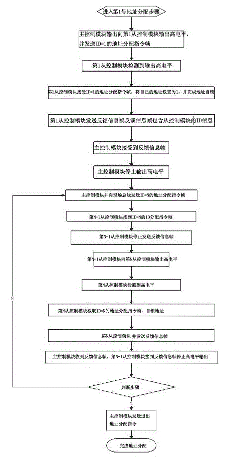
[0032] (1) Enter the No. 1 address allocation step. After the battery is replaced, connect the control part of each module and the voltage output part. After power-on, the battery management system enters the ID allocation mode;

[0033] (2) After the battery management system enters the ID allocation mode, the main control module outputs a level signal and sends an address allocation instruction frame (N=1),

[0034] (3) The battery module at position 1 detects the input signal, and the slave control module assigns ID=1 contained in the received address assignment instruction frame to itself.

[0035] (4) After the ID is assigned successfully, the slave control module is self-locked to ensure that the ID number will not be changed at will;

[0036] (5) And the slave control module sends a feedback handshake signal (feedback information frame) to the master control module, and the feedback ID allocation includes its own ID=1 information.

[0037] (6) After the main control mo...


PUM


Abstract

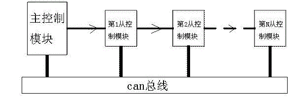
The invention discloses a method for battery module address assignment of a battery energy storage system. The battery energy storage system comprises a master control module and a natural number of battery modules. Each of the battery modules comprises a slave control module and a battery, and the mater control module and the slave control module are both connected to a field bus. The method comprises the steps of monitoring the battery modules, calculating the number of the batteries, assigning a first address, judging the steps and assigning an Nth address. The method disclosed by the invention has the following remarkable beneficial effects: (1) the field bus adopted by the method is a can bus, thereby having the advantages of high real-time performance, long transmission distance, strong anti-electromagnetic interference capacity and the like; (2) the improvement is based on an existing CAN network topology and hardware structure, thereby being low in popularization cost and high in feasibility; (3) the method has dual mistake proofing functions in the process of address assignment; and (4) the method does not need human participation, reduces misoperation, saves the labor cost, and improves operation experiences if the technology is applied to electric automobiles.

Description

technical field [0001] The invention relates to an address allocation method, in particular to a battery module address allocation method of a battery energy storage system. Background technique [0002] The battery system of electric vehicles or other battery energy storage systems requires more batteries, usually consisting of many battery modules, each of which is equipped with a separate slave controller, which is responsible for the battery Module data acquisition and communication with the main controller. When the power of the battery system is exhausted and the battery needs to be replaced, the newly replaced battery module needs to reassign the logical address (abbreviation: ID) of the battery module to exchange data with the battery management system. At present, IDs are assigned manually, which is difficult to implement for mobile electric vehicles, resulting in a waste of manpower, and the time required is unacceptable to drivers. At present, there are two main...

Claims


Application Information

Patent Timeline
Patent Type & Authority Applications(China)
IPC IPC(8): G05B19/418
CPCY02P90/02
Inventor 刘飞文锋阮旭松肖方义
Owner HUIZHOU EPOWER ELECTRONICS
Learn More