Material hoister control module
A material hoist and control module technology, applied in elevators, transportation and packaging, etc., can solve the problems of dusty construction workshops, affecting construction, and prone to accidents
- Summary
- Abstract
- Description
- Claims
- Application Information
AI Technical Summary
Problems solved by technology
Method used
Image
Examples
Embodiment 1
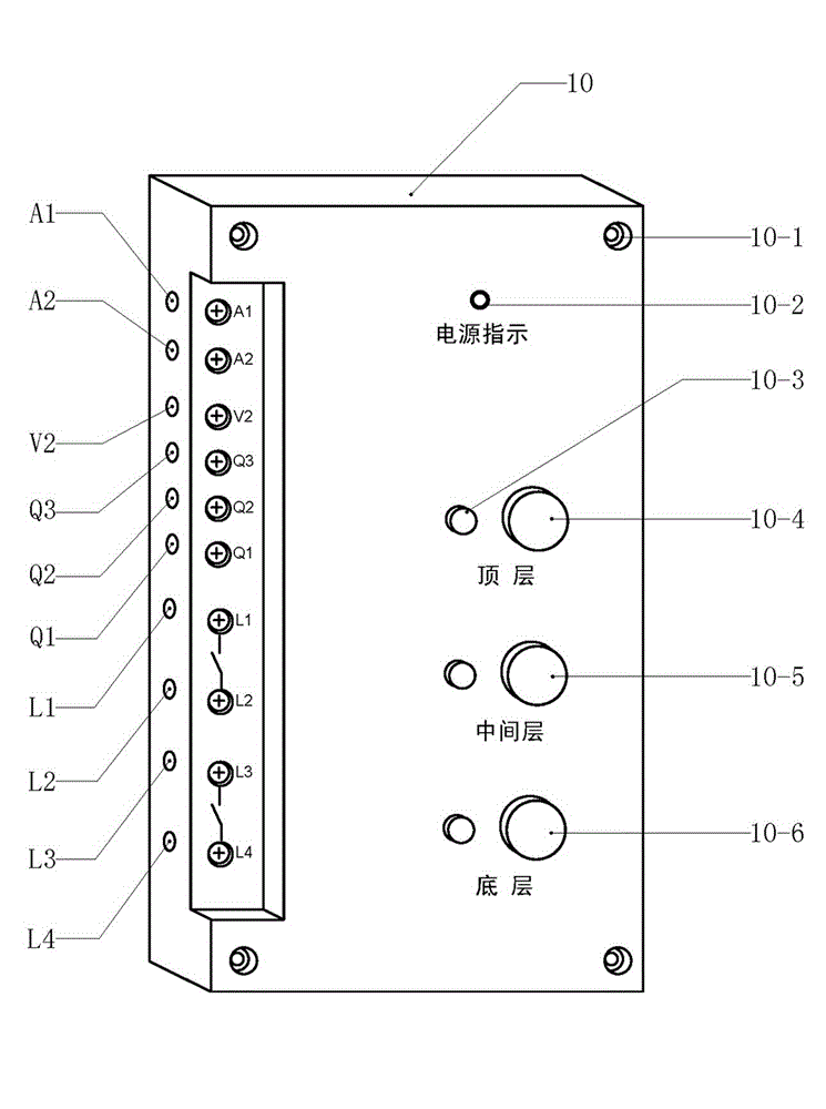
[0016] Example 1 figure 1In the embodiment shown, the control module of the material hoist is composed of a housing and an internal circuit. The internal circuit includes electronic components and a circuit board. The internal circuit is placed in the housing and encapsulated and cured with epoxy resin. There are four corners of the control module. Mounting screw holes (10-1), the buttons of the bottom button switch (10-6), the middle button switch (10-5) and the top button switch (10-4) protrude from the panel of the control module; There are power indicator light (10-2) and the indicator light (10-3) of the docking floor on the panel, and the indicator light (10-3) consists of light-emitting diode 1 (VD17), light-emitting diode 2 (VD27) and light-emitting diode 3 respectively. (VD37), the pins of LED 1 (VD17), LED 2 (VD27) and LED 3 (VD37) are connected to the circuit board; there are power input terminal a (A1) and power input on the side of the control module Terminal b...
Embodiment 2
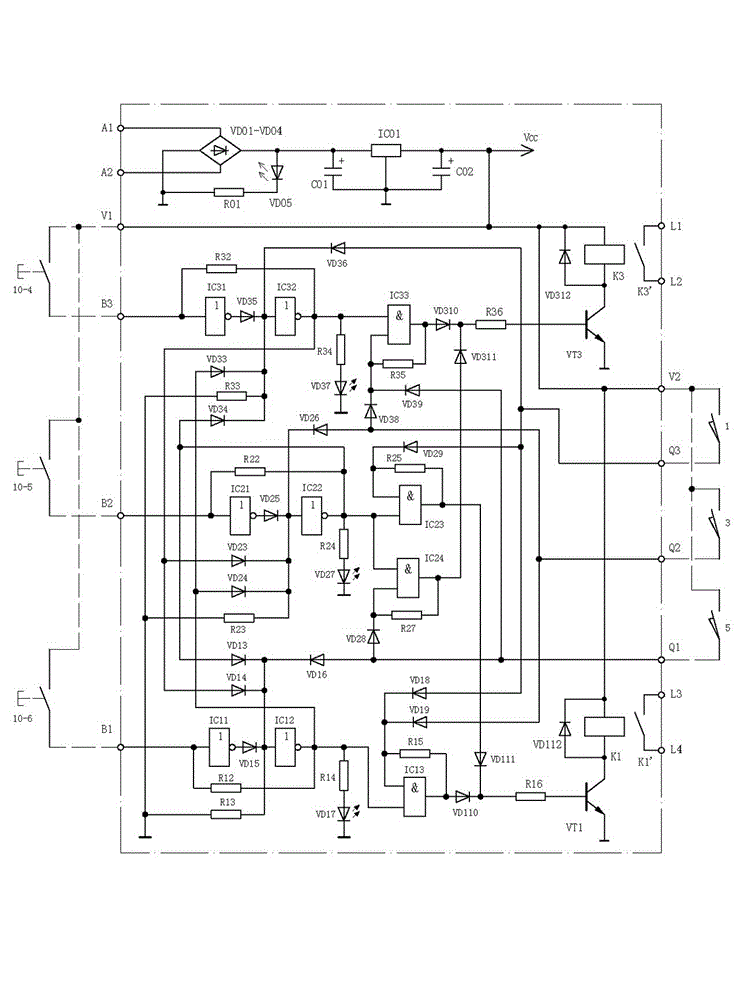
[0017] Example 2 figure 2In the embodiment shown, the internal circuit of the control module of the material hoist is mainly composed of the working power circuit, the bottom stop control circuit, the middle stop control circuit, the top stop control circuit, the up output circuit, the down output circuit, and the bottom limit switch. The interface (Q1), the interface (Q2) of the middle layer limit switch and the interface (Q3) of the top layer limit switch are composed of bridge rectifier (VD01-VD04), filter capacitor a (C01), three-terminal voltage regulator Block (IC01) and filter capacitor b (C02) constitute a working power supply circuit; it consists of bottom button switch (10-6), NOT gate 1a (IC11), isolation diode 1a (VD15), NOT gate 1b (IC12), feedback resistor 1a (R12), Interlock Diode 1a (VD13), Interlock Diode 1b (VD14), Feedback Diode 1a (VD16), AND Gate 1 (IC13), Feedback Resistor 1b (R15), Feedback Diode 1b (VD18) and Feedback Diode 1c (VD19) constitutes the b...
Embodiment 3
[0018] Example 3 image 3In the shown embodiment, the bottom button switch (10-6), the middle button switch (10-5) and the top button switch (10-4) are arranged on the periphery of the control module of the material hoist, and the bottom button switch (10- 6), the middle button switch (10-5) and the top button switch (10-4) are contact switches, the bottom button switch (10-6), the middle button switch (10-5) and the top button switch (10 The input terminal of -4) is connected to the positive pole of the working power supply, the output terminal of the bottom button switch (10-6) is connected to the input terminal of the NOT gate 1a (IC11), and the output terminal of the middle layer button switch (10-5) is connected to The input terminal of the NOT gate 2a (IC21), the output terminal of the button switch (10-4) on the top layer is connected to the input terminal of the NOT gate 3a (IC31), and the working power circuit in the control module, the bottom docking control circuit,...
PUM
 Abstract
Description
Claims
Application Information
 - R&D Engineer
- R&D Manager
- IP Professional
- Industry Leading Data Capabilities
- Powerful AI technology
- Patent DNA Extraction
Browse by: Latest US Patents, China's latest patents, Technical Efficacy Thesaurus, Application Domain, Technology Topic, Popular Technical Reports.
© 2024 PatSnap. All rights reserved.Legal|Privacy policy|Modern Slavery Act Transparency Statement|Sitemap|About US| Contact US: help@patsnap.com


