Automatic heat dissipation type free-flow electrophoresis separation chamber device

An electrophoretic separation and heat dissipation technology, which is applied to the separation of dispersed particles, measurement devices, separation methods, etc., can solve the problems of inconvenience of polyacrylamide gel membrane, difficulty in ensuring the sealing performance of the separation chamber, and inconvenient assembly of the separation chamber, etc. To achieve the effect of compact separation chamber device, improved electrical conductivity and good water leakage prevention performance

Active Publication Date: 2013-10-02
SHANGHAI JIAO TONG UNIV
View PDF7 Cites 9 Cited by
  • Summary
  • Abstract
  • Description
  • Claims
  • Application Information

AI Technical Summary

Problems solved by technology

However, this series of devices has the following disadvantages: 1. The polyacrylamide gel membrane is very inconvenient in the electrophoresis operation; 2. The electrical conductivity of the polyacrylamide gel membrane generally leads to low voltage efficiency and short use time; 3. Fastening It is difficult for the device to ensure the sealing of the separation chamber; 4. The assembly of the separation chamber is inconvenient; 5. The upper and lower plates of this type of separation device are basically made of plexiglass plates, and at the same time a cooling water cooling system is added for heat dissipation, and due to the thermal conductivity of the plexiglass plate Very low, the temperature of the cooling water needs to be very low to dissipate the Joule heat

Method used


Image

  • Automatic heat dissipation type free-flow electrophoresis separation chamber device
  • Automatic heat dissipation type free-flow electrophoresis separation chamber device
  • Automatic heat dissipation type free-flow electrophoresis separation chamber device

Examples


Embodiment

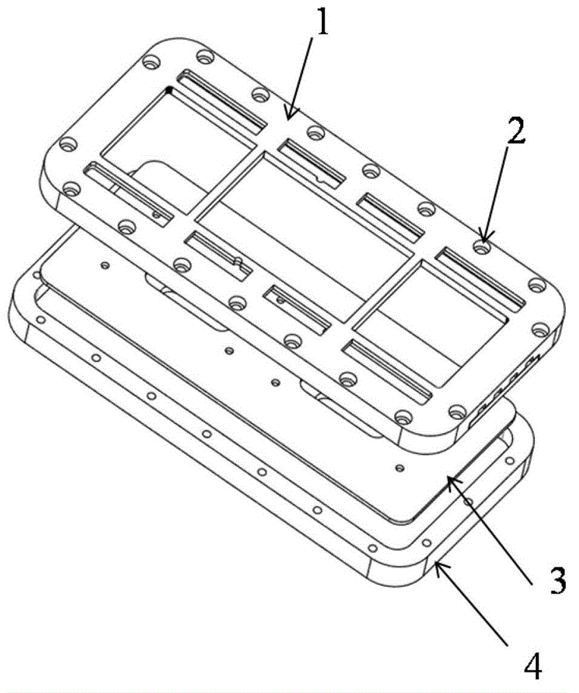
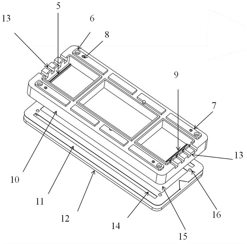
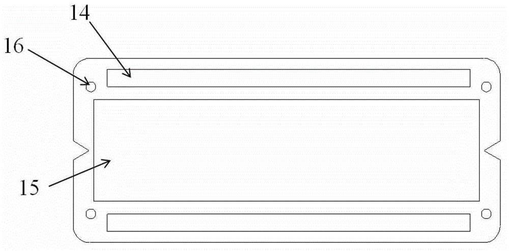
[0029] Such as Figure 1 to Figure 10 As shown, the present invention includes a semiconductor refrigeration sheet 26, an air-cooled radiator 27, a thermally conductive silica gel 28, a temperature controller 29, a DC power supply 30, a temperature sensor 31, a fastening structure upper part 1, an organic glass plate 10, and an ion membrane 11 , ceramic plate 12, rubber pad 3, fastening structure lower part 4, inlet guide plate 18 and outlet guide plate 17, semiconductor cooling plate 26, air-cooled radiator 27, thermal silica gel 28, temperature controller 29, DC The automatic heat dissipation system composed of power supply 30 and temperature sensor 31 is evenly coated with thermal conductive silica gel 28 between the semiconductor refrigeration sheet 26 and the top copper sheet of the air-cooled radiator 27, and the upper part 1 of the fastening structure, the organic glass plate 10, and the ion membrane 11. The ceramic plate 12, the rubber pad 3, and the lower part 4 of th...


PUM


Abstract

The invention discloses a free-flow electrophoresis separation chamber device used in the technical field of biochemical engineering. The device comprises an organic glass flat plate, a ceramic flat plate, an ionic membrane, an electrophoresis chamber, an electrode chamber, a fastening sealed structure and an automatic semiconductor refrigeration and heat dissipation device, wherein the ionic membrane is located between an upper organic glass flat plate and a lower ceramic flat plate, and the middle and two sides of the ionic membrane are hollowed, and the ionic membrane, the upper organic glass flat plate and the lower ceramic flat plate form the electrophoresis chamber and the electrode chamber; a plurality of liquid inlet holes are uniformly formed on one end of the upper organic glass flat plate, and double amount of liquid outlet holes are uniformly formed on the other end of the upper organic glass flat plate, thus forming a swimming lane. The device disclosed by the invention can effectively solve the problem that a separation chamber is easy to leak, can effectively eliminate joule heat in the separation chamber, can improve the stability of flowing shape of the fluid in the separation chamber, and is easy to assemble; the device can be widely used for routine free-flow electrophoresis separation of multiple types of samples such as small-molecule substances, protein, organelle and virus, and meanwhile, the device can be applied to purification of samples.

Description

technical field [0001] The invention relates to the technical field of biochemical devices, in particular to an automatic heat dissipation free-flow electrophoresis separation chamber device for preparative free-flow electrophoresis. Background technique [0002] The development of electrophoresis technology began in the early 20th century. This technology has been successfully used for the separation of various types of substances, such as organelles, proteins, polypeptides, amino acids, etc., and has been widely used in chemical biology and other fields. The support media often used in the early electrophoresis process include filter paper and cellulose acetate membrane, etc., with the development of technology, such support media are gradually replaced by gel. The advantages of easy forming of gel, easy adjustment of pore size, and the ability to recycle separated substances have greatly promoted the development of electrophoresis technology, making electrophoresis techno...

Claims


Application Information

Patent Timeline
IPC IPC(8): B01D57/02
CPCB01D57/02G01N27/44708G01N27/44769
Inventor 曹成喜颜健刘小平孔凡志杨成章李国庆李军樊柳荫
Owner SHANGHAI JIAO TONG UNIV
Why Eureka
Try Eureka