Solar energy power source double-pushing injection locking LED array lamp
A technology of light-emitting diodes and solar power supplies, which is applied in the direction of electric light sources, electric lamp circuit layout, light sources, etc., can solve problems such as nonlinear intermodulation power imbalance, avoid device temperature rise, oscillation frequency changes, prolong service life, and stabilize lighting effects
Inactive Publication Date: 2013-09-25
阮小青
View PDF5 Cites 0 Cited by
- Summary
- Abstract
- Description
- Claims
- Application Information
AI Technical Summary
Problems solved by technology
However, the phases of the power combining oscillating voltage must be the same to overcome nonlinear intermodulation power imbalance
Method used
View moreImage
Smart ImageViewing Examples

Examples
Embodiment
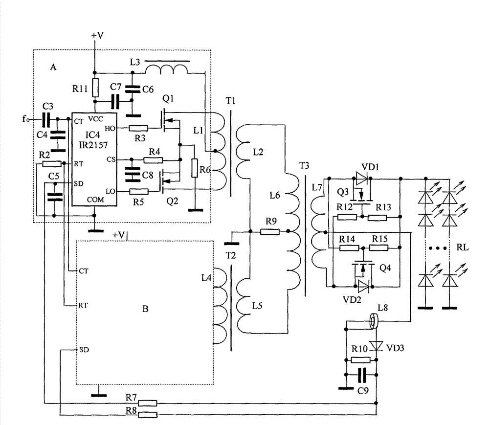
[0022] Embodiment The solar power supply voltage is 36V, the inverter current is 2.3A, and the double-push output power is combined to match the 70W light-emitting diode LED array lamp RL, the inverter efficiency is 85%, the light is stable, and the service life is long.
Login to View More PUM
 Abstract
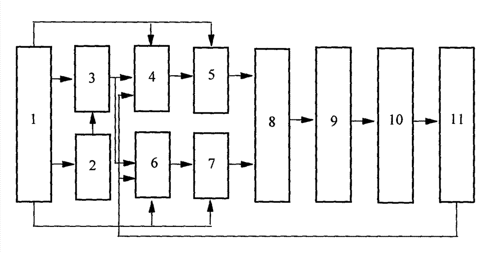
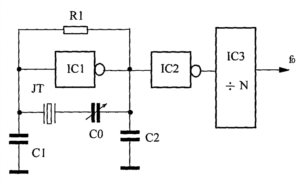
The invention relates to the technical field of electric light sources, in particular to a solar energy power source double-pushing injection locking LED array lamp. Two self-oscillation chips (4 and 6) are jointly connected with a timing resistor element R2 and a timing capacitor element C3 to generate synchronous oscillation, namely, one is the self-oscillation chip 4 and the output power transformer T1 of a push-pull inverter A, and the other is the self-oscillation chip 6 and the output power transformer T2 of a push-pull inverter B; signals are fed into an adding coupler in an anti-phase mode; power synthesis is conducted; the signals are fed to the LED array lamp in a full-wave rectification mode. Signals of a benchmark crystal oscillator are injected into RC oscillators of the two self-oscillation chips (4 and 6) through a frequency divider to enable phase positions to be locked, lamplight descending caused by excessive temperature rising, oscillation frequency changes and power imbalance of a device is avoided, and the service life of the LED array lamp is prolonged. The solar energy power source double-pushing injection locking LED array lamp is suitable for lighting occasions powered by solar energy power sources with the low voltage and the large current.
Description
technical field [0001] The invention relates to the technical field of electric light source lighting, in particular to a solar power source double injection lock light-emitting diode LED array lamp. Background technique [0002] In the prior art, electronic transformers generally use LC or RC oscillators as the light source of light-emitting diode LED array lamps. The oscillation frequency generated is poorly stabilized by temperature changes, which affects power instability and decreases in light intensity. Especially solar-powered light-emitting diode LED array lights work in Low voltage, high current, although the electronic transformer for DC-AC-DC inverter is simple in structure and low in cost. Due to the low power supply voltage, it is necessary to increase the device current to obtain high-power lighting, resulting in a sharp increase in the power consumption of the oscillating power tube and an excessively high temperature rise, resulting in a change in the oscilla...
Claims
Login to View More Application Information
Patent Timeline
 Patent Type & Authority Applications(China)
IPC IPC(8): H05B37/02
Inventor 阮树成阮小青
Owner 阮小青
Features
- R&D
- Intellectual Property
- Life Sciences
- Materials
- Tech Scout
- Unparalleled Data Quality
- Higher Quality Content
- 60% Fewer Hallucinations
Learn More Browse by: Latest US Patents, China's latest patents, Technical Efficacy Thesaurus, Application Domain, Technology Topic, Popular Technical Reports.
© 2025 PatSnap. All rights reserved.Legal|Privacy policy|Modern Slavery Act Transparency Statement|Sitemap|About US| Contact US: help@patsnap.com