Antenna plane near-field test scanner

A scanner and plane technology, which is applied to the field of near-field test scanning devices for antenna planes, can solve the problems of improving positioning accuracy, increasing accuracy and speed, and failing to realize closed-loop control, and achieves the effects of convenient installation and debugging and simple mechanism.

Inactive Publication Date: 2013-09-25
南京顺仕祥电子有限公司
View PDF4 Cites 14 Cited by
  • Summary
  • Abstract
  • Description
  • Claims
  • Application Information

AI Technical Summary

Problems solved by technology

[0003] Using stepping or servo motors as the drive requires the use of motion conversion mechanisms such as screw, guide rail, gear, rack, and reduction box, which are likely to cause system errors and need to be corrected by interpolation to further improve accuracy and speed. difficult to achieve
[0004] Using the stepper motor drive method, because the closed-loop control cannot be realized, the improvement of positioning accuracy is limited
In addition, the speed response of the stepping motor is not high, and it is difficult to achieve fast start and stop
[0005] Using the servo motor drive method, although closed-loop control can be realized and the response speed is also high, but the motion conversion process is required, so there is a backlash problem, and the system construction will be more complicated to achieve high-precision positioning control

Method used


Image

  • Antenna plane near-field test scanner
  • Antenna plane near-field test scanner
  • Antenna plane near-field test scanner

Examples


Embodiment Construction

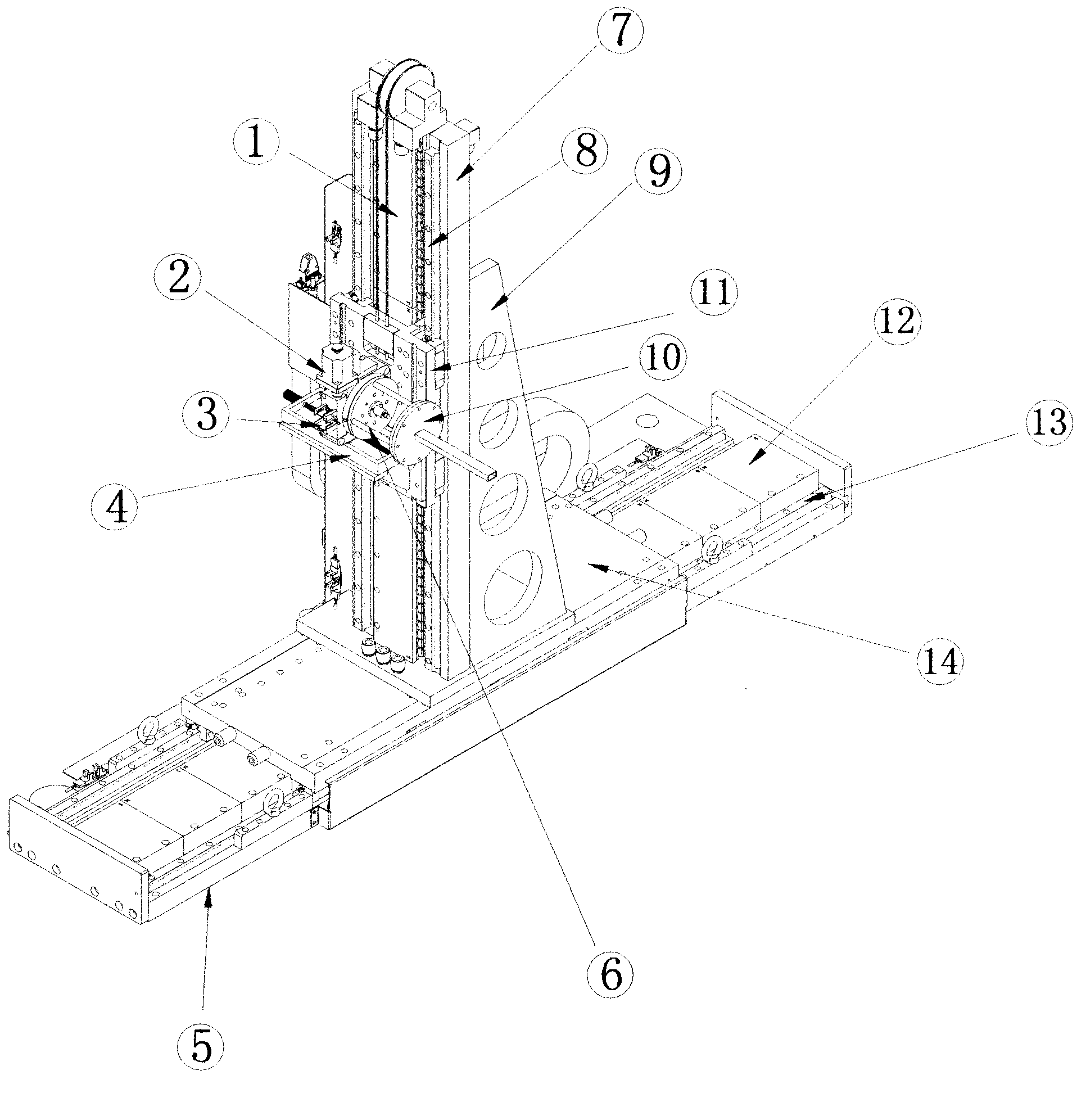
[0014] exist figure 1 Among them, the X-axis guide rail (13), the X-axis linear motor stator (12) are installed on the X-axis base (5), the Y-axis tower (7), and the Y-axis support plate (9) are installed on the X-axis linear motor mover (14). ), the Y-axis guide rail (8) Y-axis linear motor stator (1) is mounted on the Y-axis tower, the Z-axis linear platform (4) is mounted on the Y-axis linear motor mover, the P-axis one-dimensional turntable (2), and the P-axis is mounted on the turntable Squirrel cage (6) (squirrel cage-shaped support), probe (10) is installed on the squirrel cage.

[0015] Working process: Under the control of the driver, the X and Y linear motors can drive the probe to do two-dimensional movement, and the P-axis one-dimensional turntable can also rotate. The data measured by the probe can be transmitted to the PC in real time through the cable and position signal.

[0016] exist image 3 , shows the system control block diagram, the control system is c...


PUM


Abstract

An antenna plane near-field test scanner adopts a brand-new design and is composed of a direct drive motor (a linear motor for short) serving as a drive element and an industrial personal computer and a position measurer serving as control units, as well as a probe and a PC (personal computer) serving as data sampling units. In an antenna plane near-field test, in particular a millimeter wave antenna test, a space plane is scanned with high precision at a high speed and antenna near-field amplitude-phase data is sampled at the same time. The linear motor is used as the drive element for driving the scanner to move in X and Y directions, a screw rod, a gear wheel, a rack and a speed reducer are not used, a load is directly driven, and an error such as a back clearance is eliminated. The advantage of closed-loop control is brought into fully play, accurate and high-speed positioning is realized, and the needs of the millimeter wave antenna near-field test can be well met.

Description

technical field [0001] The invention relates to a scanning device for antenna plane near-field testing, which can be used in general wave bands, and is especially suitable for millimeter-wave antenna near-field testing, and is a high-precision, high-efficiency antenna plane near-field testing scanner. Background technique [0002] At present, with the continuous development of microwave technology, especially the wide application of millimeter wave, higher requirements are put forward for the scanner in the antenna near-field test: to achieve fast response while ensuring high-precision positioning. Since the wavelength (λ) of the millimeter wave is only 1-10mm, and the sampling point spacing of the planar near-field scanning is required to meet the sampling rate ≤λ / 2, when the scanning area is large, it is necessary to obtain a large amount of dense sampling data. The stepper and servo motor drive methods have deficiencies both in terms of positioning accuracy and sampling s...

Claims


Application Information

Patent Timeline
Patent Type & Authority Applications(China)
IPC IPC(8): G01R29/08
Inventor 姚跃吾孙跃东张迎庆
Owner 南京顺仕祥电子有限公司
Why Eureka
Try Eureka